Saturday, March 10, 2018

Bottineau Grain Train

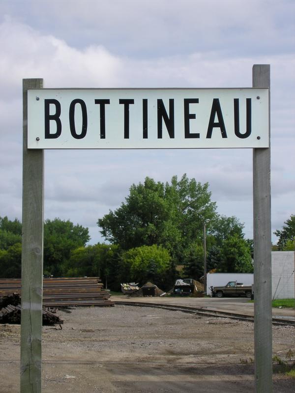
Station sign Bottineau

In the summer of 1991 I took a trip to North Dakota with my brother, sister, mom and stepfather to visit my grandparents at their home in the quiet town of Bottineau. We caught the county fair, played at the lake, visited the family farm and played lots of card and dice games. Even thinking back to the pre-internet world that probably sounds boring, but my grandparents were a fun couple who loved to laugh and dote on their grandkids.

After our vacation concluded and we were about to leave, I chose to stick around and hang out with my grandparents for another week. I had graduated high school and didn't have anything pressing to do that next week, so why not? I'm really glad I was able to spend that time with my grandparents and get to know them as a young adult about to start college.

Anyway, there wasn't a whole lot going on during the lazy days so I chose to grab my sketch book and draw. I was going to be starting on a degree in fine arts in a few weeks so I was determined to draw what I could around town.

Like many small towns in North Dakota, Bottineau is home to a grain elevator complex situated alongside a railroad branchline. It wasn't long before I was drawn to the facility and began to study it. I took in the cylindrical and prismatic structures, the piping and wires connecting the various buildings, the contrast of the older sheet metal clad wooden elevator and the modern slipformed concrete silos and head house. Some things I can still remember clearly: the coolness of the shadows against the radiant concrete in the high sun and the ripples and waves in the slipformed walls when the evening sun set the buildings afire with red light.

And then one morning a train arrived.


Two geep thirty-eight types pulled fifty-two empties into town followed by a caboose. The train rolled into town quickly, then paused and started off again. The crew cut the crossings and tied the train down in four cuts, then stashed the power behind the depot. Before I knew what was going on the crew hopped in a taxi for a ride back to Minot.

In Texas I was used to the trains near my house flying by on the main, or coal trains struggling up the hill, or when things would get congested holding off crossings waiting for a light to get into town. The trains I'd see in Saginaw seemed static as we'd fly over the yards on the freeway. Even the jobs working the elevators and mills seemed to always be at lunch. I certainly hadn't seen anything like this.
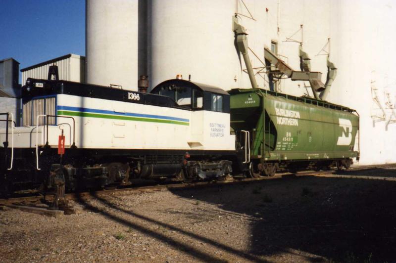
ILSX 1366 and BN 454511

There wasn't much down time before the elevator crew fired up the old SW1 and started spotting cars in cuts of three at the barley house and at the durum house. As each car was loaded the switcher shoved them down the storage track, filling it up and eventually having to cut the crossings. Throughout the day and into the next the process repeated until the loaded train was set up in four cuts ready to be put back together and air tested.

I missed the train getting put back together, but I did see the caboose roll away behind the train and disappear into the twilight as the crew dragged it through the fields of grain down to Rugby to rejoin the main line.

It occurred to me that this process repeated itself over and over again. There was no time to rest, not for the rail crews that brought the empties in or took the loads out, not for the drivers bringing tractors, pickups, wagons and semi-trailers full of grain to the elevators, and certainly not for the switch crew at the elevator, who now had given up their switch engine duties to join in the effort to refill those silos.

Trucks lined the streets waiting for their turn through the head house. Fans and motors and machines made a constant droning sound around the complex. Clouds of grain dust floated in the air tinging everything with gold. The town was filled with that warm scent of cut summer grass.
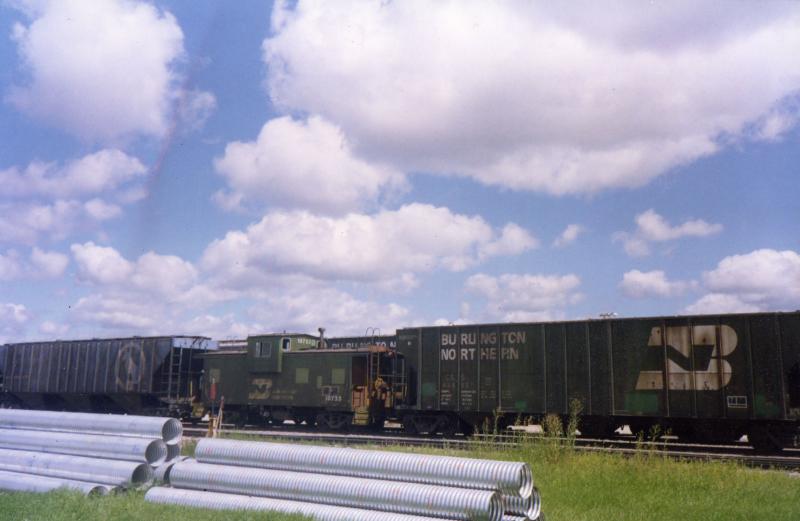
21 years after the merger and still seeing Big Sky Blue

I had sketched and I had photographed and I had taken notes. I had a record of the locomotives, the railcars and the caboose that came to town and left. As many times as this process must have happened in towns across the midwest every day it seemed really insignificant. But those are the things nobody ever seems to take down, and soon they fade away as if they never happened. Two small town elevators combine into one complex. One town thrives and one fades away. Whatever would happen I wanted a record of that week.
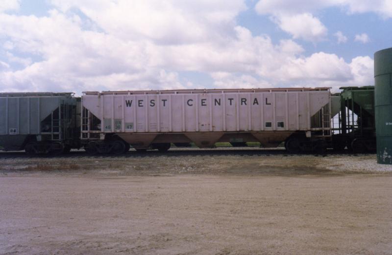
Besides pre-merger hoppers, BN was grabbing every retired co-op car they could

It wasn't long before I began to make models based on those photos and notes and sketches. I soon became aware that exact models simply weren't available for most of the cars. And by exact, I mean as far as I knew there were rib side three bay hoppers and there were cylindrical shaped three bay hoppers. I could tell there were differences between many of them - some "missing" ribs in key places, some with high or low sides, some with a barrel shaped body and others almost completely cylindrical like a tank - but I didn't know how the differences broke down into capacity or manufacturer. But over time two things happened: I learned who made which car and manufacturers like Accurail, Intermountain and Model Die Casting brought out models to supplement the Athearn Pullman Standard and ACF hoppers that made up my first attempts at this train.

I took a crack at the caboose using a factory painted Athearn model. I eventually realized the Athearn model is too short, that it's a flawed model of a Rock Island caboose and not much of a match for the BN caboose I saw. Eventually I bought an Atlas caboose. Much better!
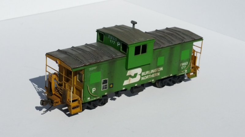
Atlas caboose modified with one of my 3D printed cupolas

Same thing with the locomotives. I bought two Athearn GP38-2s, one in BN green and one in Conrail blue. I fired up my airbrush and coated everything with a cloud of mud colored dust. It was brutal. Those locomotives eventually got stripped and repainted, then again stripped and cut up to become a pair of Mopac GP38-2s I still need to finish... I found a shell at a train show that looked pretty much how I remembered the ex-Conrail geep, so I bought it and found a drive for it. I picked up an Atlas GP38 decorated for BN later on.


Time for some updated photos!

Over the years I've replaced nearly every car I originally bought to make a model of this train. Some of them have been repurposed into models for this train and some for other subjects. More manufacturers have produced even more models, so I'm able to dial in the models closer and closer to the real thing. I even became a manufacturer myself of sorts when I worked up parts to model the caboose more accurately. I've covered some of the cars modeled in my blog previously, here, here and here.

To this day, nearly twenty-seven years later, this train remains a work in progress. I'll probably never finish modeling it. But by pursuing it, I keep it alive. I keep that summer alive. Making big bets at the card table in my grandma's house doesn't seem that far away.

My brother and I, both of us are engineers now

Now that I've been an engineer for some time, I can relate so much to that crew that tore into town, cut that train up and flew back to Minot in the cab. How many times have I done the same thing itching to get out of the seat and make it home for some time with the wife and girls before they go to sleep? Yes, you still have to dot all the I's and cross all the T's and do it safely, but an experienced and motivated railroader can do it quickly.

The older I get the less I rush like that. There's too much you can miss if you do. You end up doing it twice or more unless you take your time and move with purpose. You only learn that the closer you get to finishing something, when you can finally see your mistakes, missteps and oversights.

Who knows? Maybe one day I'll eventually get it right.
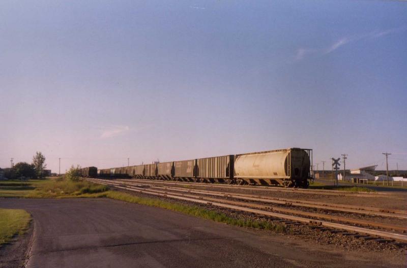
Friday, March 2, 2018

GE Kitbashes

I have a soft spot for GE locomotives if it isn't already clear. This comes from operating them for a living. The Dash 9s and GEVOs I run every day are powerful, responsive and reliable. It wasn't always that way, though. I don't think anyone disputes the bad reputation GE's Universal series and to a lesser extent the Dash 7 series earned. But once GE started listening to customers report problems, especially as they became involved in solving these problems, things started to turn around.

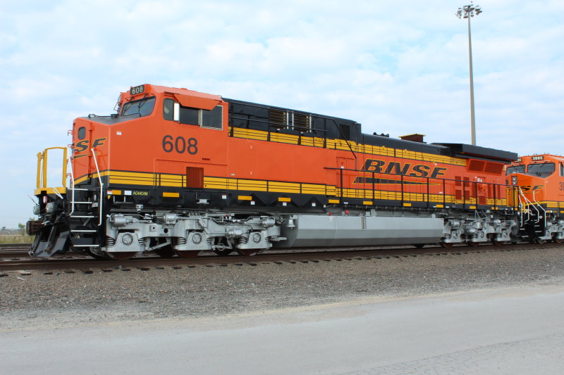
Real life kitbash: AC4400C4M AC four motor conversion from C44-9W ATSF 608

A big change in railroading was effective dynamic braking. As long as there was an occupied caboose at the rear of the train, train handling meant keeping the slack stretched to avoid throwing your conductor and brakeman out of their seats. To accomplish this the engineer would make a minimum reduction and drag the train over hogbacks and shallow valleys. As dynamic braking technology improved the timing couldn't have been better. New crew consist labor agreements and legislation made cabooses go away for most Class I trains. This freed up the engineer to control the slack without dragging brakes, something the railroads were very interested in because of the massive fuel savings potential, greater average speed, and a lower risk of sticking brakes, flat spots, hotboxes and other problems with the train.

Dynamic brakes had previously been more of a mountain grade feature to augment air braking on long downhill runs than a tool you'd use to control speed on flatter terrain. By themselves they weren't enough to keep heavy trains under control. But through the 70s and 80s the technology was developed to increase their effectiveness and to lower the minimum speed they were effective. With these new capabilities engineers were able to transition between throttle and dynamic braking frequently.

Back when dynamic brakes were used primarily on long descending grades, there weren't many scenarios where the diesel engine would be running hot and demanding cooling from the radiators at the same time the dynamic brakes were dissipating braking force in the form of releasing heat energy through the resistor grids. Therefore it made sense to locate the resistor grids near the radiator where you already had a large fan and intake grilles. But once the ability to transition frequently between throttle and dynamic braking was available, the diesel engine didn't have time to cool while the resistor grids kept the radiator hot. This led to relocating the dynamic brake resistor grids and cooling fans ahead of the diesel engine, first seen on Burlington Northern's second order of B30-7A cabless booster units and C36-7s delivered to Missouri Pacific and Norfolk & Western.

As the use of dynamic brakes moved outside the realm of mountain grades, they became more powerful and more cost-effective to use. Along with the adoption of computer control systems of the diesel engine and electrical systems, design elements of the locomotive had to change to hold up under the new normal extreme operating conditions. These improvements in part led to the Dash 8 series, the wildly successful Dash 9 series and finally to today's Evolution series.

GE wasn't alone in innovation. EMD also computerized their engine and electrical systems around the same time. Like GE, EMD took a new approach with the dynamic brakes on their 50 series locomotives and again with the 80 and 90 series, relocating and improving them each time.

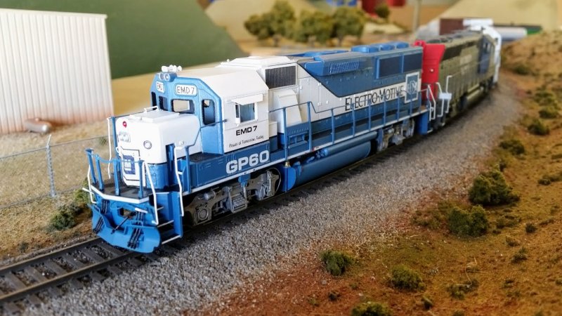
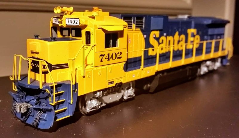
When GE unveiled a new locomotive series it looked like each new design was nothing more than the old Universal series locomotive under layers of bolted on parts. Let's face it: aesthetics were never part of GE's design philosophy when it came to locomotives. Form follows function period. Compare this to General Motors' Electro-Motive Division, where styling was part of the identity of the company from the Corvette to the Cadillac. Look at the homely hodgepodge of a locomotive, the GE B39-8 demonstrator. Compare this to the sleek and aerodynamic EMD GP60 demonstrator, its direct competitor. If looks matter, it's not even a fair fight. But when it came to achieving fuel efficiency, higher horsepower and putting that horsepower to the rail, GE won.

EMD 7 GP60 Demonstrator

ATSF 7402 GE B39-8 Demonstrator

As a modeler it always looked to me like GE simply kitbashed their latest design using parts from previous models. The basic Universal series locomotive had a distinctive cab with a rounded roof, a snub nose and a plain long hood with a rounded roof contour echoing the lines of the cab. This plain hood was punctuated with the occasional grille and a large radiator at the rear. The improved Dash 7 series was just like the Universal series, but with the largest of the large U33 radiators extending out over the walkway. As production carried on Dash 7s had the dynamic brake housing separated from the radiator and moved to a "bump" in the auxiliary cab roof. This bump carried through to the early Dash 8 series and was incorporated into a boxy hood between the operator cab and the engine compartment. U33 radiators were changed out for larger angled Dash 8 radiators.

The Dash 9 series saw the end of the four axle diesel, the standard cab, and the simple angled fuel tank with reservoirs at each end. But with that end came the adoption of large outside coil spring trucks and optional AC traction technology. In the midst of all that was the old Universal series hood covering the engine compartment. Everything else had changed, but that hood was still there (though angled instead of rounded). That feature finally went away with the Evolution Series, along with the Dash 8 radiator, but still around were the comfort cab, the Dash 8 auxiliary cab, the big trucks and the Dash 9 fuel tank.

The apparent modular nature of GE locomotives makes them ideal modeling subjects, especially with so many nicely detailed and great running models from Atlas. The U23B drive and body shell can be combined with the U33C drive and shell to build a U33B, U36B or a U23C. Before Atlas released the B23-7 and B30-7 models, I cut down a C30-7 shell into a B23-7. I had enough trouble with the Bachmann drive -- in particular the trucks -- that I stopped work on the model. The release of the Atlas B23-7 model finally stuck a fork in this project. But the concept was proven, that with enough slicing and dicing the raw materials were there in the Atlas shell parts to build a variety of models.

GE B23-7 from Atlas C30-7 long hood and nose, Atlas U23B cab and Bachmann B23-7 frame and sill

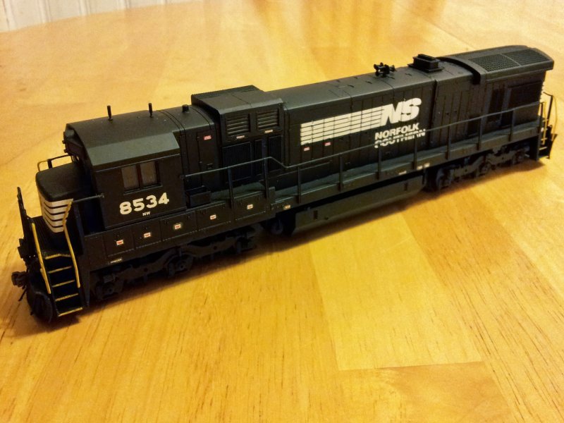
Of course 3D printing has opened up an entirely new set of possibilities using modular components to either cut into the Atlas shell or even replace entire parts. I mentioned building a model of a late C36-7 in my Norfolk & Western clasp truck blog. At the time I didn't address the stacked horizontal radiator intake grilles because there was no good source of the grilles. I couldn't figure out how to scratchbuild them or where I might get something reasonably close to cut in. Besides, the model is painted black. Who can even tell? I finished the model in January 2014 and moved on.

GE C36-7 as NW 8534 from Atlas C30-7, Smokey Valley and Hi-Tech Details parts

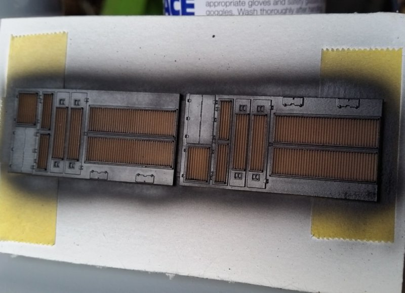
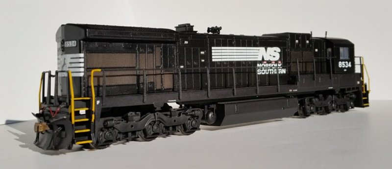
A couple years later it occurred to me I could use the translucent nature of 3D printed acrylic parts to model the see-through nature of the corrugated screen grilles on GE locomotives. I drew up some replacement panels for the area under the radiators on the Atlas model and printed them. I painted them lightly with a dirty brown color, just enough to tint the grilles, then I masked the grilles front and back and painted the rest of the parts the black body color. Installed on the model they look great. If you hold the model up to a light you can see the light come through the grilles. Of course the large metal weight mounted to the frame blocks most of the light, but as a concept it's solid.

NW C36-7 radiator parts available from my Shapeways store


Since then I've designed other hood parts, fuel tanks, air reservoirs, cabs and frames. I'm even working on a body kit for Burlington Northern B30-7A booster units. Where will this end? Who knows? But I'm pretty far from the end right now. There are a lot of models and variations to cover -- and kitbash -- yet.

Sunday, February 25, 2018

Norfolk & Western's triple clasp GEs

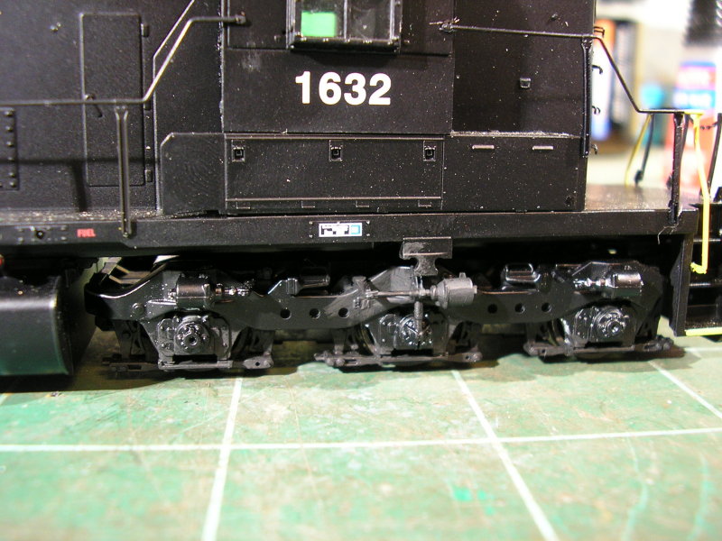
Norfolk & Western may be best known as the last railroad to retire their steam locomotives and replace their locomotive fleet with diesels. In the diesel era they were known as one of the last railroads (along with future merger partner Southern Railway) to purchase high short hood locomotives. When other railroads had embraced the idea of using a J-relay valve in the locomotive's independent brake system to produce greater brake cylinder pressure against a single brake shoe per wheel, Norfolk & Western stayed the course of using clasp type brakes and lower operating brake cylinder pressure. Evidence of this could be seen in the trucks used on N&W's six axle diesels. The twelve brake shoes per truck gave them a distinctive look.

I modified a couple Athearn SD40-2s to have clasp type brakes a few years ago. I covered those models in my blog here. The modification to the Athearn trucks is pretty easy and it can be done using either Blomberg trucks or Flexicoil switcher trucks to donate the brake shoes, although the Flexicoil switcher trucks will also provide the brake cylinder with the long push rod. It also helps that the Athearn sideframes are made from styrene, which is easy to cut and splice and glue together.

Triple clasp sideframes on Athearn RTR SD40-2

It's another story entirely if you're modeling anything GE, with the exception of the last order of C36-7s. In fact, not having the ability to model the Adirondack clasp type sideframes found on N&W's U30Cs, C30-7s and early C36-7s is the reason I chose to model one of the later C36-7s. Atlas originally made two different sideframes for the U33C and C30-7 models, which they called GSC and Adirondack sideframes after the casting foundry of each prototype. However, Atlas mislabeled the parts which caused great confusion for people trying to get the "correct" version for a particular model.

Atlas GSC C30-7 sideframe

Atlas Adirondack C30-7 sideframe

When Atlas came out with the U30C, another style of sideframe was offered. This time it was a later Adirondack sideframe with low mounted brake cylinders.


This style of sideframe holds the most promise for someone wanting to build some N&W clasp style sideframes. It has the correct shape overall as well as in the area over the brake cylinder lever. Unfortunately the brake cylinder lever at the top of the sideframe exists only to tie onto the handbrake chain, so this shape is only found on the left axle when looking straight at the sideframe. You'd need this shape along with a mirror image of it to cut and splice these sideframes into models of the clasp type, and that's assuming you could actually get the slick engineering plastic the sideframes are cast in to glue back together.

These sideframes, like the National Uni-Truck II (found on some Trailer Train Front Runners, Southern's Autoguard articulated autoracks and under the ends of Burlington Northern's Trough Train articulated coal hoppers) represented something of a holy grail for me. Once I became familiar with the idea that 3D printing could reproduce fine enough details in a durable enough material for modeling I knew I had to take up the challenge to create a CAD model of them.

It's one thing to decide to make a 3D model of something rare and unique and quite another to find enough reference material to make it happen. What was frustrating about these sideframes (and the Uni-Truck II) was they really weren't that rare, they just weren't considered worthy of film during their day. In the digital photography age you just click!-click!-click! until you get the shot. When everyone was shooting film unless you had it in mind you were going to burn a roll or two on detail shots you took your best shots only, well-composed and well-lit. Roster shots of good and poor quality abound from the film era and are easy to find online from a variety of sources. But detail shots of the kind I needed are not so easy to find. If these prototypes still existed in their as-built form today it would be a simple matter of tracking them down and taking some detail photos.

That's actually how the story ends for the National Uni-Truck II. There is a single example of a Front Runner equipped with National Uni-Truck II trucks at the National Museum of Transportation in Kirkwood, Missouri, TTOX 130059. Detail photos of this car provided the information I needed to create the CAD model of the trucks that I ended up printing and offering for sale in my Shapeways store.

3D printed National Uni-Truck II trucks with Intermountain wheels installed on Walthers Front Runner

With the Norfolk & Western U30Cs, C30-7s and C36-7s I wasn't as fortunate finding an example to photograph. I'm not certain on the disposition of all of these locomotives, but many that I've found were shipped overseas after their useful lives here in the United States. Once they arrive at their destination it's not uncommon for them to be converted to a B-B B-B configuration and have the C trucks discarded. I put out a request for photos on discussion forums and email lists a few times over the years but I didn't get a response. That is until the very end of 2017 when Jay Barnaby and Scott Marion hooked me up with some detail photos from their collections. These turned out to be the shots I needed to create 2D drawings.

Some discussion on this topic with Andy Harman was very helpful, too. With the straight-on shots taken care of it became a priority to determine the depth of the features: how much did the brake cylinders protrude from the sideframes, how far did the reinforced section over the center axle protrude, and so forth. More photos were shared and analyzed. And finally in the midst of reverse-engineering the Atlas sideframes to create a drop-in fit of a sideframe I had enough to develop the 3D model.


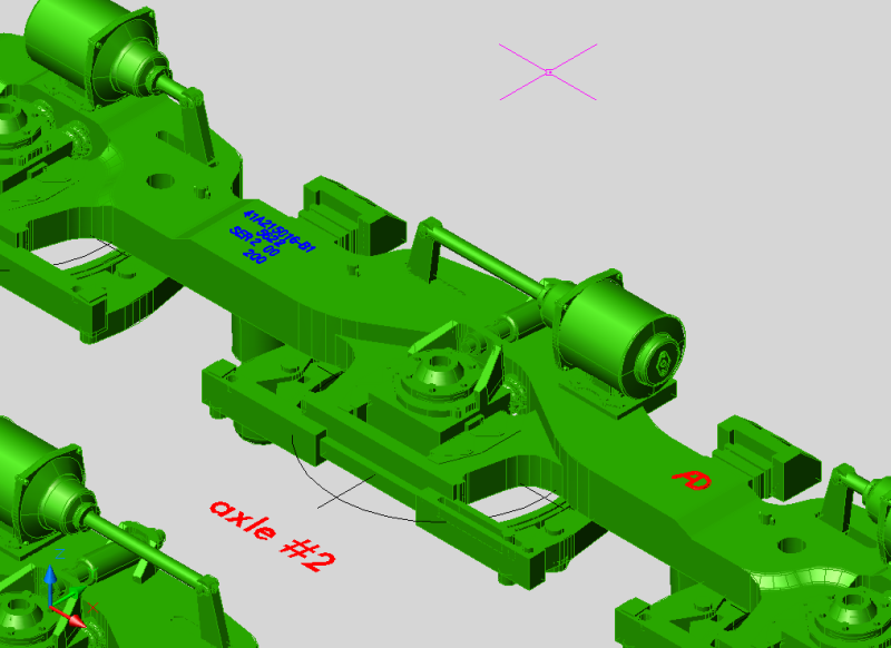
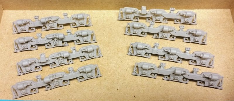
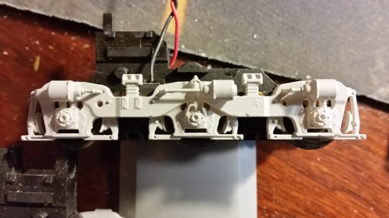
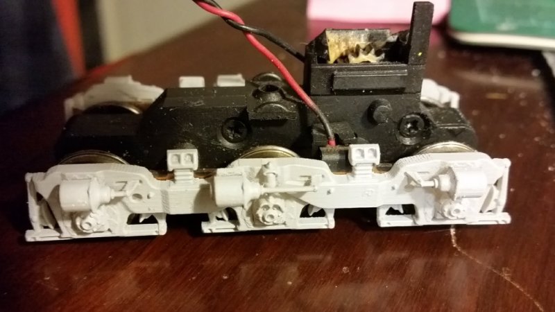
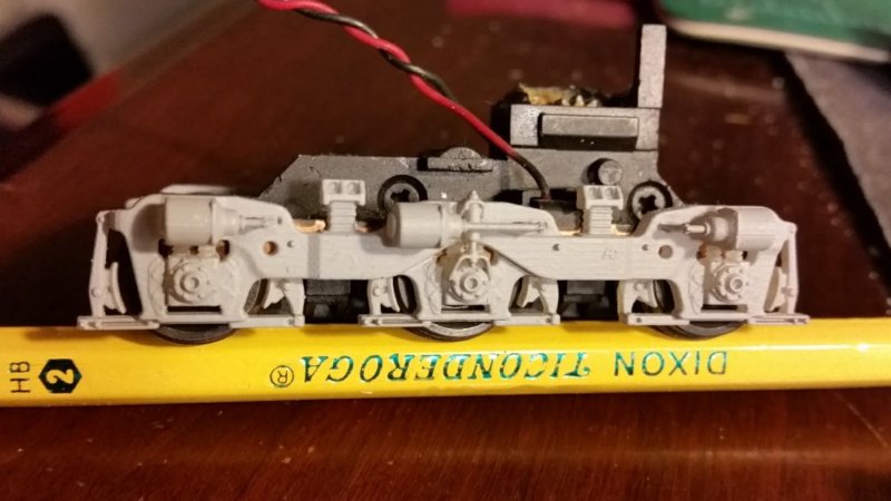
Here's where I screwed up (there's always that part): I created what may be a perfectly reverse-engineered 3D model of an Atlas GE three axle sideframe. Then I proceeded to install brake rigging on the base sideframe model that fouled the copper pickup and bearing strips that held the axle ends in place, thus preventing the installation of the printed sideframes. Well, that's what prototyping is for! (that's what I tell myself when I screw up with a design) What I should have done is create a 3D model of the truck with the copper pickup strip and checked the fit of the sideframe into the truck model in CAD, not after printing the design. Fortunately, I didn't have to modify the back side of the sideframes much and there was still enough material to hold the brake shoes and levers in place after I removed the material fouling the copper strips. I immediately revised the CAD files to remove this interference.

First printed prototype U30C and C30-7/C36-7 sideframes

Spending all this time working on these clasp sideframes helped me get to know both the Atlas model and the prototypes pretty well. One thing I found interesting about the Atlas model -- and I'm not sure what the reason is for this little nugget of joy -- is the axle spacing in the C truck found on the U33C, C30-7 and U30C. I'm sure it has to do with the prototype of the U33C or C30-7 trucks originally tooled in the 90s by Atlas. The difference is so minor that it probably just wasn't worth addressing when it came time to release the U30C. But it is significant enough that putting the wrong sideframe on the wrong truck will result in a sideframe that won't fit without modification. You'll also notice the bearing detail isn't centered on the center axle and wheelset.

On freight cars there is a B end and an A end. Looking at the B end you have a left and right side. Axles are numbered from the B end to the A end. Similarly, locomotives have a front and a rear. The front is designated by a letter "F" stenciled near the stepwell on the sides of the locomotive nearest the front. Ever the oddballs of the bunch, some Norfolk & Western and some Southern locomotives had their long hoods designated the front, which is in contrast to nearly every other railroad. Fortunately on these GE six axle units the front is the short hood where the operator cab is located. So, when you're looking at the front there is a left side and a right side. Axles are numbered from front to rear.

The prototype uses trucks with a wider spacing between axles 2 and 3 and a narrower spacing between axles 1 and 2. On the rear truck this arrangement is mirrored on the U30C and C30-7, with the greater spacing being between axles 4 and 5 and the lesser spacing between axles 5 and 6. The prototype C36-7 has the same front truck axle spacing as the U30C and C30-7, but the rear truck is reversed. It is not mirrored by the fuel tank. Instead, the front truck is identical to the rear truck. That is, the distance between axles 1 and 2 equals the distance between axles 4 and 5. Likewise, the distance between axles 2 and 3 equals the distance between axles 5 and 6.

The axle spacing on the model is just like the C36-7. This means on the model there is a distinct front truck and a rear truck; the axle spacing is not mirrored by the fuel tank.

If you look at prototype photos of U30Cs and C30-7s, the brake cylinder over the center axle points toward the fuel tank and toward the brake cylinder over the axle nearest the fuel tank. The axle spacing is greater between the two axles with brake cylinders pointing at each other than the spacing between the two axles with brake cylinders pointing the same direction. So if you're following this convoluted description, there is a problem. The axle spacing of the rear truck on the Atlas model will not work with the U30C and C30-7. The Atlas model is actually perfectly set up for the C36-7 since the brake cylinder over the center axles points toward the rear of the locomotive and the axle spacing matches the prototype. But to accurately model the trucks on either a U30C or a C30-7 the rear truck must be a mirror image of the front truck. The easiest way to do this is to replace the rear truck with another front truck. Fortunately, these truck gearboxes are easy to come by direct from Atlas. [Kudos to Atlas for continuing to make parts available and for making them inexpensive. I owe a lot of my GE kitbashes to being able to get Atlas parts.]

I figure that of the handful of others who wish to model N&W U30Cs and C30-7s, only a few will be willing to swap out the rear truck for another front truck. So for those who want to keep the drive stock and simply swap sideframes, I've made a version of the clasp sideframes set up to fit the Atlas drive as-is. For those who want to go crazy and swap rear trucks, I've made a version for them, too.

Finally, here is an image to describe the problem and solution. The sideframes depicted below illustrate the modified parts designed to fit an Atlas model that has not been modified with a front truck replacing the rear truck.


To accommodate the model, the sideframe depicted in the bottom of the image has been modified to match the axle spacing but have the general arrangement of the prototype. You can see the slight difference in distance between the brake cylinder cutouts over axles 2 and 3 and over axles 4 and 5, with 4 and 5 being closer together. On the prototype C30-7 and U30C, the bottom truck should be a mirror image of the top truck.

I'm exhausted from explaining that. You can imagine how exhausting it was to discover during the design process and create a solution for it.

After going through all that, I'm going with the extra front truck on my C30-7 model. Here are the C30-7/C36-7 sideframes:


And here are the U30C sideframes:


Printed Adirondack sideframe compared to Atlas GSC sideframe

One benefit of working up these sideframe designs with such a limited audience is I realized this basic Adirondack design was found elsewhere, namely on early C30-7s purchased by Union Pacific and the C36-7s purchased by Missouri Pacific. It didn't take much effort for me to modify the design to match each prototype.

screenshot of Adirondack sideframe CAD file as seen on early Union Pacific C30-7 locomotives

screenshot of Adirondack sideframe CAD file as seen on Missouri Pacific C36-7 locomotives

One of these days I'll try to run down all the prototypes that used some version of this basic Adirondack truck casting...

Saturday, February 24, 2018

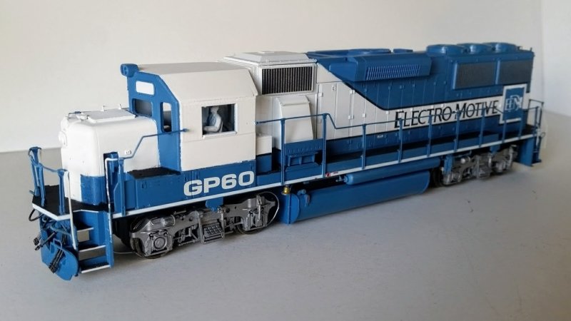
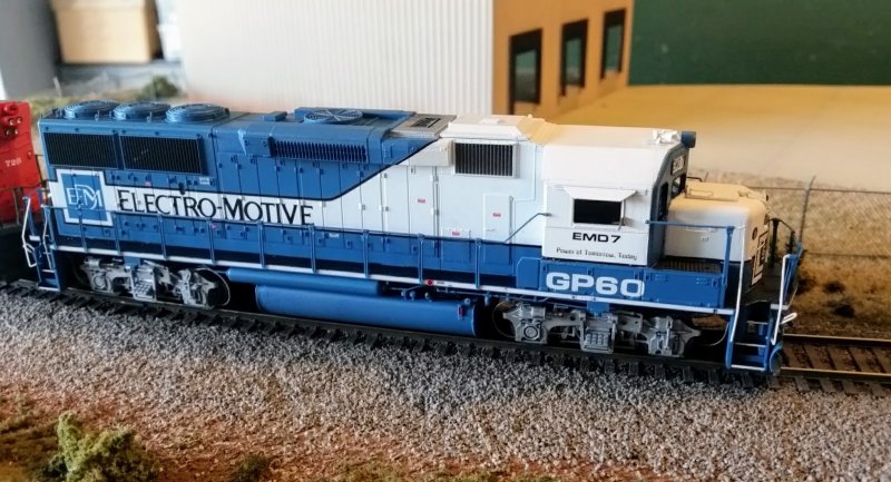
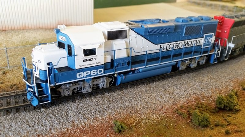
GP60 Demonstrator EMD 7

When EMD introduced their four axle 60 series to the world, they did it with six demonstrator locomotives painted in the attractive blue and white scheme worn by the SD60 demonstrators and later the Oakway SD60 lease fleet. The three GP59 and three GP60 locomotives had another feature not seen since the GP30: an aerodynamic cab with a pointed cab face. The hood corner radius of the nose was increased from the standard 4" to 9" and the standard 4" radius was applied to the leading edges of the cab. The effect of the streamlining was a striking appearance, accentuated by the color scheme.

The demonstrators made their way across the Santa Fe and Southern Pacific systems among others. In an attempt to make the locomotives ready to serve any railroad they were equipped with many of the options specified by different railroads, including a variety of different fuel fillers, extended range dynamic braking, a cab air conditioner, auxiliary warning headlights and a UDE light.
The extended range dynamic braking hatch was larger than on previous models and protruded about a foot from the hood sides. The rounded edges and sloped faces of the streamlined cab were continued to the dynamic hatch. Although none of the railroads that purchased production GP59s or GP60s opted for the streamlined cab, all were equipped with the large dynamic hatch. Eventually the streamlined styling of the hatch was discarded for a much simpler to fabricate version with squared edges and flat faces. No production GP59s received the streamlined dynamic hatch, but ATSf 400-4019, SP 9600-9619 and SSW 9621-9634 were so equipped. All others had the later, angled hatch.

After the demonstrators made their case for EMD to the prospective railroads, the GP59s were sold to Norfolk Southern and the GP60s were on a long term lease with Southern Pacific. Eventually the GP60s were returned to the lessor, sold to another lessor, then finally sold to CSX as their 6897-6899.

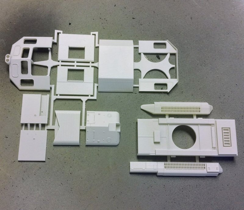
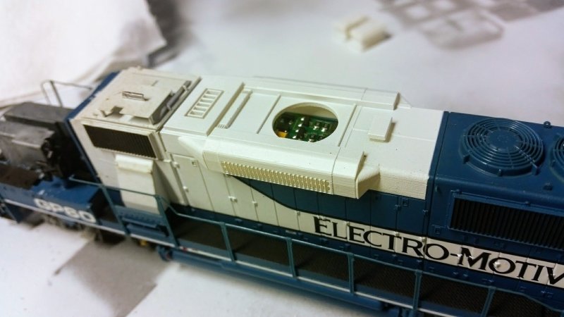
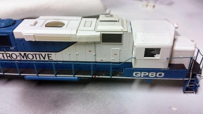
I modeled one of the demonstrators by drawing the hatch and the cab/nose combo in AutoCAD, then 3D printing the model through Shapeways. I applied the parts to a factory painted Life-Like Proto2000 GP60 model. I had to shorten the fuel tank at the rear to better match the prototype, but otherwise I just painted and decaled the new parts to match the factory paint, added a few fuel tank details, a new horn, and some cab mirrors.

I sell these parts on Shapeways, along with many others, and one of the modelers who purchased these parts noticed an error in the dynamic hatch with the size of the exhaust. Wouldn't you know it, I transposed some numbers while drawing the part. I have since revised the dynamic hatch, but at this point I have not replaced it on the model. Thanks to Roderick Quebral for his keen eye and help with this hatch and the SD40-2 hatches I drew in recent months.

Friday, February 23, 2018

GE Universal Series/Dash 7 Series Cab

From the U33C and C30-7 models released in the 90s to the U30C, U30B, B23-7 and B30-7 released in the 2000s to the newly released U33B and U36B, Atlas has done more than anyone else to fill holes in the rosters of those modeling GE locomotives of the 70s and 80s. To a large extent Atlas gets these models "right" as far as dimensional fidelity to the prototypes is concerned. Having said that, one area Atlas has fallen down is the cab.

I've read where others have pointed out the issues with the Atlas cab but I couldn't ever find any hard data on what was wrong. The front face of many of the cabs looks wrong - windows too small, windows too big, funny shaped doors, numberboards and headlights that look squeezed or in the wrong place. Nothing about the cabs seems right, but what specifically is wrong? Then there's the Hi-Tech cab, a nice little kit with several options. But I've read people have issues with it, too. So who got it right?

First of all, I set out to find some hard data on the prototype. First choice would be some nice straight-on photos of the cab and some overall measurements. I figured I could proportion out the dimensions of the windows and numberboards with the right photo and a good known measurement. The problem is you're not likely to find a position to photograph a locomotive cab where anything is straight-on since most photos are taken from ground level. Eventually I found Bill Kaufman's locomotive simulator website which features some cool simulators he built using old GE cabs. I asked him if he could measure across his simulator or provide me with a photo taken straight-on. He did one better than that, way better. Bill shared with me some cab drawings from GE that answered all my questions. I was able to create my own CAD file from the scans Bill provided. I also made CAD files of the various Atlas and Hi-Tech cabs.

The early U33C models came with one of two cabs: standard front face window arrangement and SP "L window" arrangement.


The first run C30-7s had cabs with open auxiliary side windows or the later version without the auxiliary windows.


Between the two models all the cabs had windows that were off in size and location. The most obvious issue was the top of the cab door and top of the engineer's front window were even with the top of the center windows. The size of the numberboards and both the size and shape of the headlight housing was also off. The shape of the door differed between the front and rear cab face (Atlas seemed to execute the door better on the back of the cab than the front though the size of the door window was off).


The second run of C30-7s addressed the position of the windows, but they were still undersized. The rounded headlight housing was squeezed too thin and was undersized.


Across all of these versions of the GE cab, the central rounded portion of the roof was too wide and the angled outer portions were flat instead of rounded.

Hi-Tech made several detailed GE cab kits similar in design to Cannon's line of EMD cab kits. The flat kit design incorporating thin walls, separate doors and detail parts made it easy to build a nicely detailed kit.


Hi-Tech also offered a version of the four window cab with plugged auxiliary windows, an effect not convincingly pulled off by Atlas when they simply painted over the glazing in the auxiliary windows.  I corrected this on some of my Atlas cabs by cutting in the Hi-Tech cab sides:


In spite of the nicely executed details and well proportioned windows of the Hi-Tech cab, the roof suffered from the same problems as the Atlas cabs from the U33C to the C30-7 to the U30C, only with an even wider central curved section. The narrow numberboards were also a problem with the Hi-Tech kit.

When Atlas released the B23-7 and B30-7, the cab was a new design unlike the models preceding it. The numberboard/headlight housing was a separate part, the cab base on the engineer's side had a noticeable difference in height just as the prototype and the proportions of the windows, cab doors and roofline matched the prototype much closer than previous attempts.


The headlight housing is still too narrow and the headlight assembly is mounted too low between the numberboards, but still not bad.

Before I get too far ahead of myself, let's take a look at these cabs and compare them to the prototype. In light of the errors in the cab windows of the first C30-7 cab, it's not even worth considering. But the later C30-7 cab, the Hi-Tech cab and the B23-7 cab are all worth looking at.

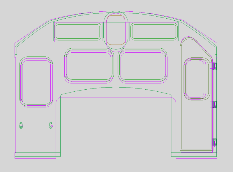
Here is a drawing of the prototype overlaid on a drawing of the Atlas 2nd run C30-7/U30C cab. The prototype is in green, the Atlas cab is in red:


Here is the prototype, again in green, compared to the Hi-Tech cab in blue:


And finally the Atlas B23-7 cab in purple compared to the prototype in green:


So, between the three, the Atlas B23-7 cab is good enough, right?

I'd use it if I could.

Trouble is, like the B23-7/B30-7 fuel tanks, the cabs aren't readily available as spare parts from Atlas. So what to do if the one good cab isn't available and all the others that are readily available have serious issues?

I initially thought I could cut in the good parts of the Hi-Tech cab into the Atlas U30C cab. But there's really no way to get the side walls of the Atlas cab thin enough to allow the front and rear Hi-Tech walls to fit without a ton of work. Then the roof is still wrong. And I'd still need a source for the numberboards since as bad as the Atlas numberboards are the Hi-Tech numberboards are worse. I wanted to avoid 3D printing not because of the quality possible but because of the cost. I figured a detailed printed flat kit like the Hi-Tech kit would cost around twenty bucks, which means I would be spending hundreds getting my fleet up to par. But as long as the Atlas B23-7 cab is so hard to find, it seems like printing is the next best solution.


An advantage printing the cabs offers is the ability to create versions of the cab that were specific to particular locomotives, such as the Santa Fe B23-7s with nose-mounted air conditioners and antenna ground planes or Southern Pacific's "L-window" cabs that were fixed to accept two panes of glazing in place of the single large L-shaped glass. The other advantage is the cab isn't close to the prototype, it is a scaled down version of the prototype. The green outline in the prototype vs. model images is not just the drawing of the prototype, it's the CAD file I used for the model. So aside from the limitations presented by the materials I'm using to print the cabs, these things are as close as I can get to the real thing.

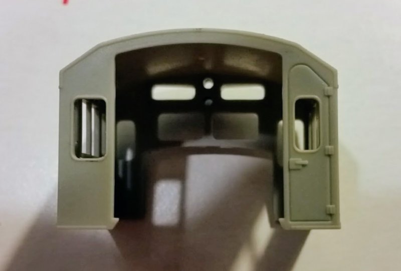
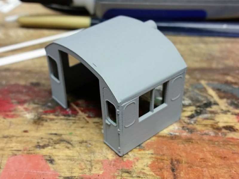
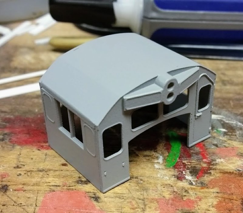
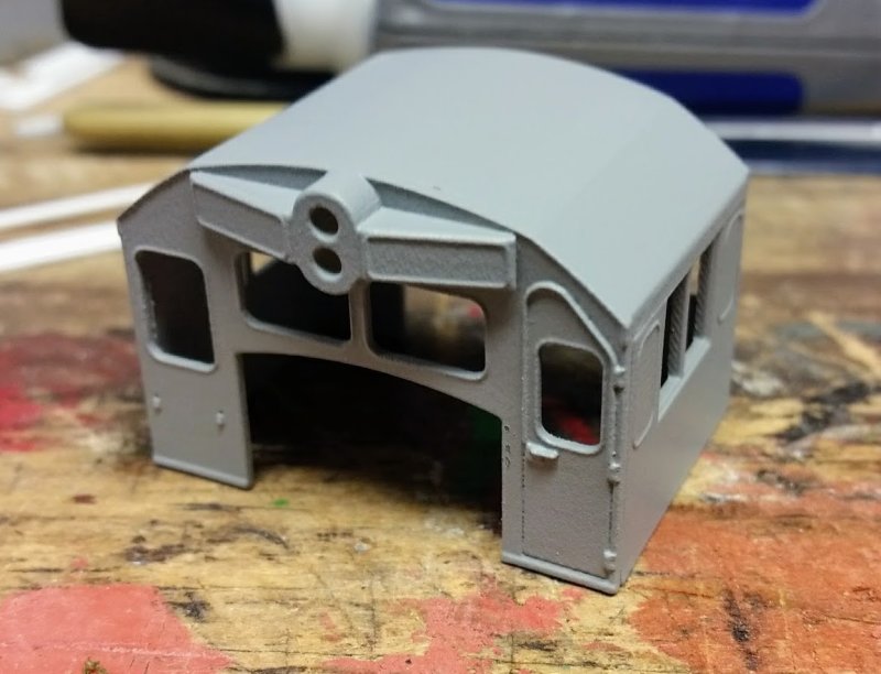
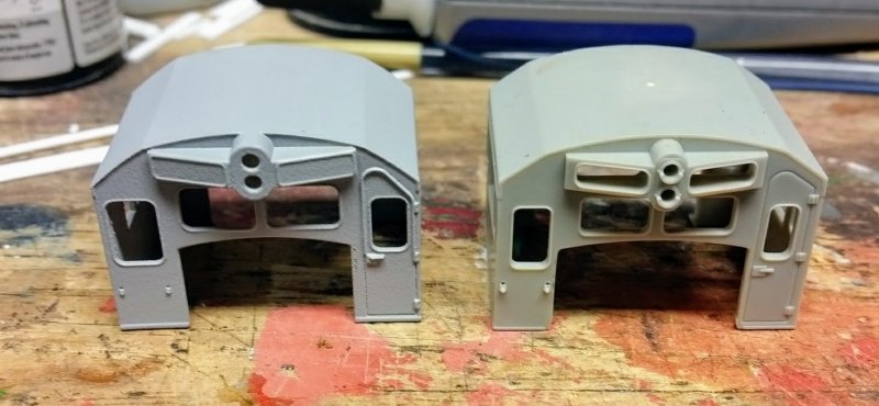
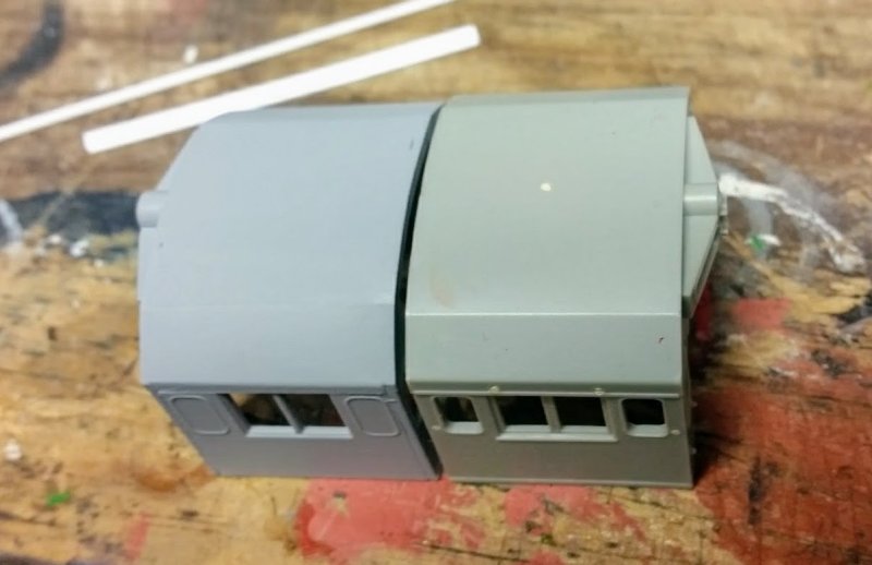
Here are a few shots of the first printed prototype:


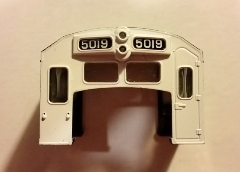
Compared to the Atlas U30C cab:


3D printed GE cabs in several variations are for sale in my shop at Shapeways:

https://www.shapeways.com/shops/he6agon?section=Diesel+Cabs&s=0