Showing posts with label Norfolk & Western. Show all posts

Tuesday, October 4, 2022

GE Kitbashes Part II

Phase 3


Not the Rapido B36-7


Now that Rapido has delivered the B36-7 in HO scale, the Phase 3 Bxx-7 frame is a reality. Atlas already covered both Phase 1 and Phase 2 frames with their B23-7 and B30-7 models. So what exactly are the differences between the Phases? The big change is the frame length and truck centers, even though it's a pretty small change as locomotives go.

Michael Eby's Dash 7 Phases page contains a wealth of information. Michael cites Will Davis and David A. Davis' blog for some in-depth prototype information. To recap Michael's data, the Phase 1 frame is 62'-2" over the pulling faces with truck centers at 36'-2". The bolsters in Phase 1 are 13'-0" from the pulling face of each end. Phase 2 kept the same length frame, but moved the rear truck one foot closer to the coupler for 62'-2" overall, front truck 13'-0" from the pulling face, rear truck 12'-0" from the pulling face and 37'-2" truck centers. Phase 3 shortened the frame by one foot overall, bringing the pulling faces, pilots and stepwells six inches closer to each end and and bringing the rear truck in a corresponding six inches for 61'-2" overall, front truck 12'-6" from the pulling face, rear truck 12'-0" from the pulling face and 36'-8" truck centers.

What does the Phase 3 frame do for us in HO scale? Aside from the B36-7, with the Rapido model there is now a frame for late B23-7, B30-7, B30-7A and B30-7AB models. The Southern B30-7A1 is its own thing on a frame different from everything else, but the Burlington Northern B30-7A1B units share a Phase 3 frame with the earlier B30-7AB.

The Rapido models aren't cheap -- nothing in HO scale is at this point anymore -- so who's going to use them for kitbash fodder? Not me I can tell you that! But some folks might be motivated to tear off the shell of their model and replace it with something else to help them model a B30-7A or a late B23-7 or one of the B-unit versions Burlington Northern had. If I were a betting man I'd put money on Rapido offering these models on their B36-7 frame at some point in the future. In fact, when they were showing the test shots of the B36-7 they hinted at these future releases by showing fuel tank variations tooled for Missouri Pacific and Burlington Northern, neither of which had the B36-7. 

So if not Rapido, what's the path to modeling a Phase 3 Bxx-7? 


The Method


Long before I'd ever heard of the Rapido model I worked up some drawings of the various Phase 3 hoods. One thing led to another and I started drawing some Phase 1 and 2 hoods. And fuel tanks. And details. Anyway, Atlas got a few things right with their Phase 1 and 2 models, so I didn't see any reason to reinvent the wheel there (at first). In particular I liked the way the radiator was rendered with cores molded as part of the body and a photoetched metal screen insert with frame that snaps in place on the radiator. Now that KV Models offers an etched part for the Atlas U33C/C30-7 radiator, which is larger and better proportioned than the B23-7/B30-7 radiator, I've begun adapting this etched part to a revised 3D printed radiator section. 

Atlas is to be commended for their B30-7 cab. I covered what makes it good and where it misses in a previous blog. They have also recently started delivering their U33B/U36B model with a revised cab that addresses these shortcomings. I couldn't wait for that so I designed a cab with better fidelity to the prototype some time ago. It comes with numerous options covering the Universal Series through the end of Dash 7 production. I started printing these cabs as flat kits through Shapeways but over the past year or so I've been printing one-piece resin versions.

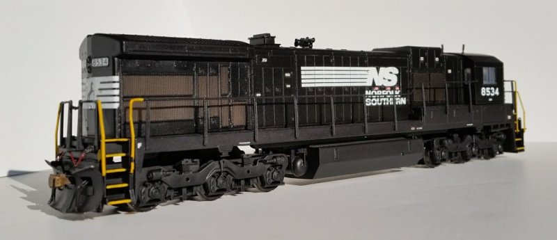
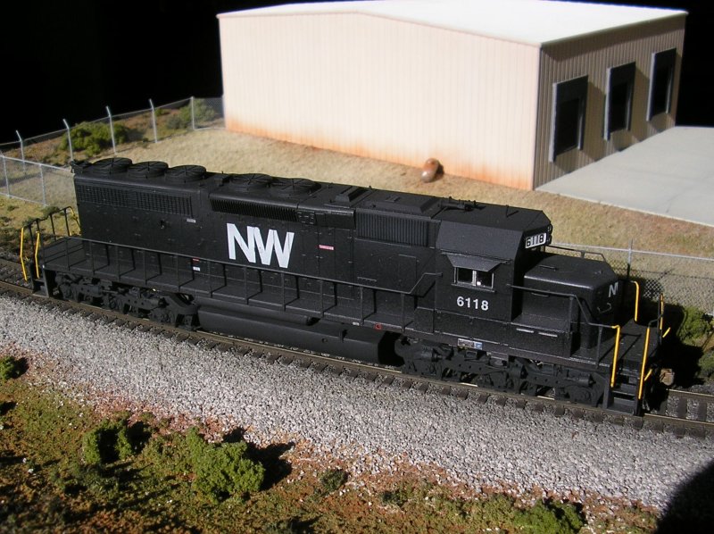
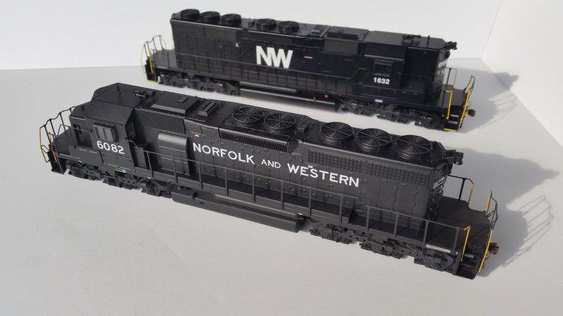
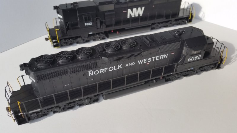
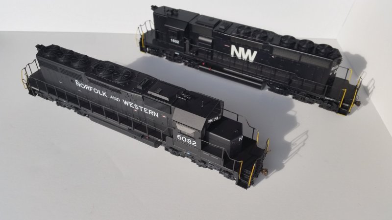
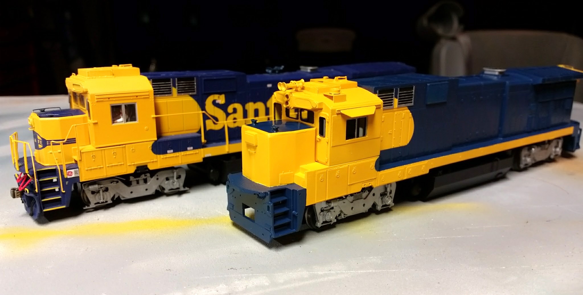
Now as far as the rest of the Atlas model is concerned -- the hood contour, the heaviness of latches and other details, the fuel tank and reservoirs, the high short hood -- well, not so good. These things are passable in a factory painted model I suppose (nope, not that high short hood), but after kitbashing the Southern Pacific B36-7 above from an Atlas C30-7 body I figured I could do better. This has led to a lot of drawings of Bxx-7 hoods. A LOT of drawings.

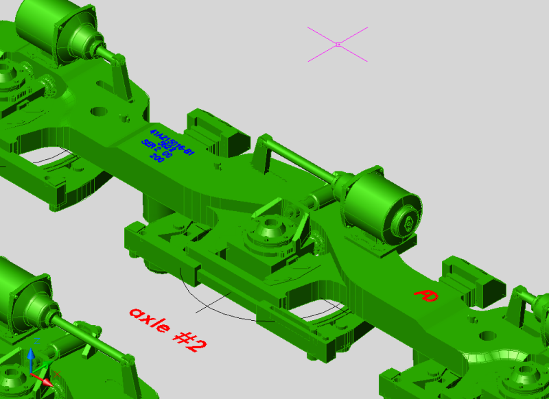
GE B36-7 B-unit wreck rebuild, one of many drawings


The Atlas sills are also very nice and they are easy to shorten by cutting out six inch sections near the stepwells. The B36-7 kitbash makes a good case for using the Atlas sills in a Bxx-7 build. The Southern B30-7A1 is it's own thing worthy of its own blog, but was also able to make use of the Atlas sill by lengthening it just aft of the step down from the battery boxes. Phase 3 sills have a "long, short, long, long, long" pattern of access doors on the conductor's side under the cab, compared to the Phase 1 and 2 pattern of "panel, short, short, long, long, long" access doors. This is easy to model using a donor sill to harvest the long access doors. However, this process of cutting up spare sills gets a little old and mistakes can be made, so I've been drawing up variations on the sills to be able to print every version without cutting anything. Again with more and more drawings.

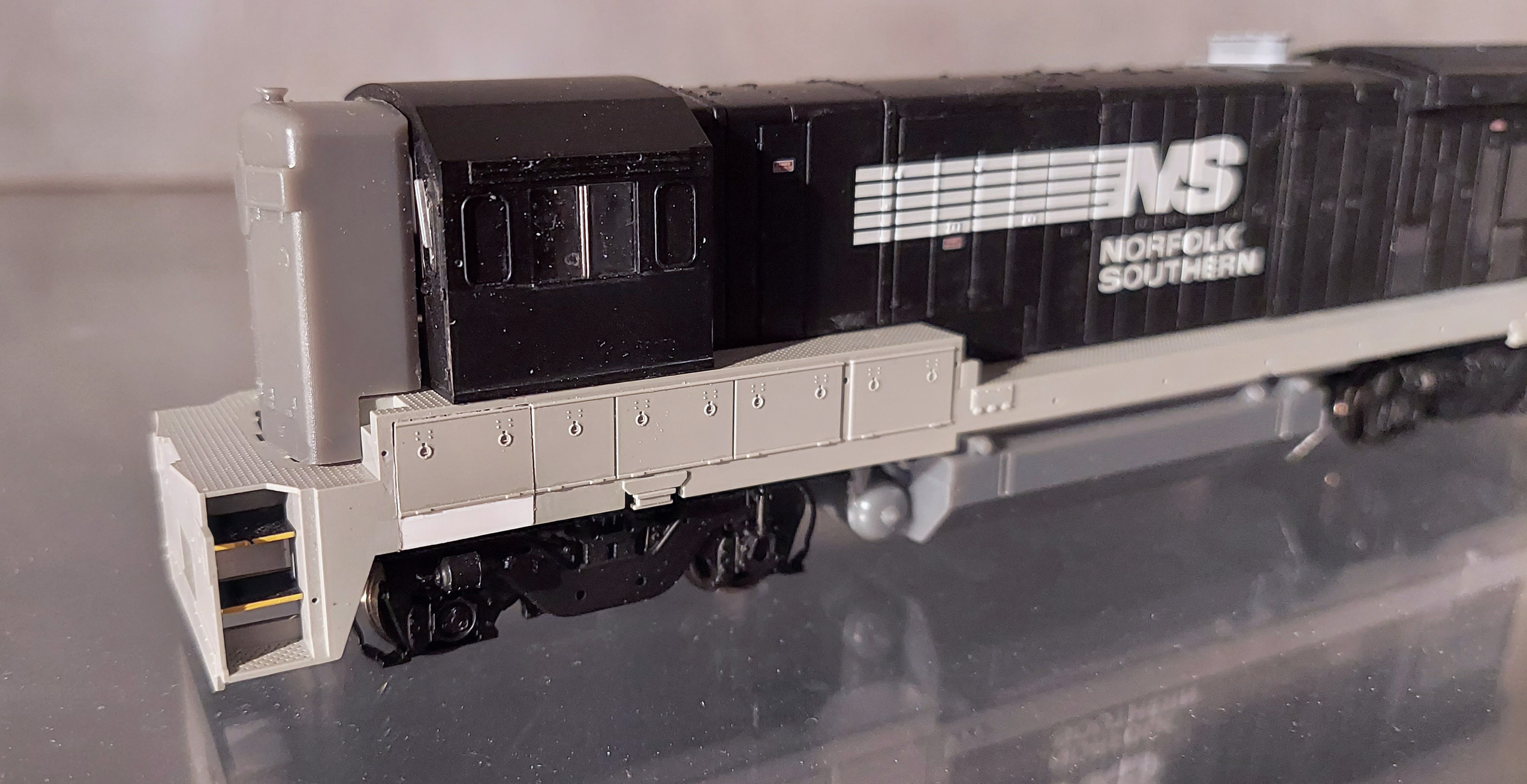
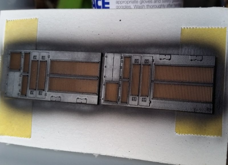
Atlas Phase 2 subbase modified to Phase 3 (moving the stepwells inboard remains to be done)


So if I'm keeping the Atlas sill and radiator part, what am I replacing? Everything else. Well, almost. I do like using the Atlas coupler boxes. But who knows? I might start printing those, too.


The Frame


This is the wildcard that prevents using an Atlas frame. The Phase 3 frame is not only shorter in length, but the truck centers are different from both Phase 1 and Phase 2. I've seen other people scratchbuild frames out of brass or cut up diecast frames and piece them back together with pins, screws or strong glue. I could probably muddle my way through one or more of those methods but I doubt I could make it repeatable. So instead I dealt with custom frames by drawing them in 3D and printing them in nylon through Shapeways. This allowed me to model the B39-8 demonstrator, B36-7 and create a dummy frame for a spare Atlas Phase 1 shell I had. This method also allows me to model any frame with any truck centers, which means models are on the table now that only existed as demonstrators or were built for only one railroad.

Shapeways' nylon is a rough material but it is strong. It also doesn't present an opportunity to show detail so the fuel tank and reservoirs are printed as separate parts to cover the frame much in the way a pretty or exotic veneer wood is used to cover a less expensive and less attractive substrate wood. The nylon material does not offer much weight though so it has to be added somewhere. My first attempts to fill the fuel tank area with weight resulted in the frame sagging, so it became clear the frame would either have to be reinforced or the weight would have to be located in the body shell. The thicker frame seemed to do the trick but it still couldn't support much more weight than the Kato HM-5 motor and drivetrain so I glued lead bird shot into the inside of the body shell.

First generation nylon frame with Life-Like P2K Athearn-clone AAR B trucks designed for Atlas B30-7 fuel tank


The first variation on the frame involved using the laser cutting vendor Send Cut Send. I was able to get thin sheets of stainless steel cut to my dimensions for a good price. I removed a corresponding amount of thickness from the nylon frame model and glued the frame to the steel part. The fit was excellent since both Shapeways and Send Cut Send do very precise work.

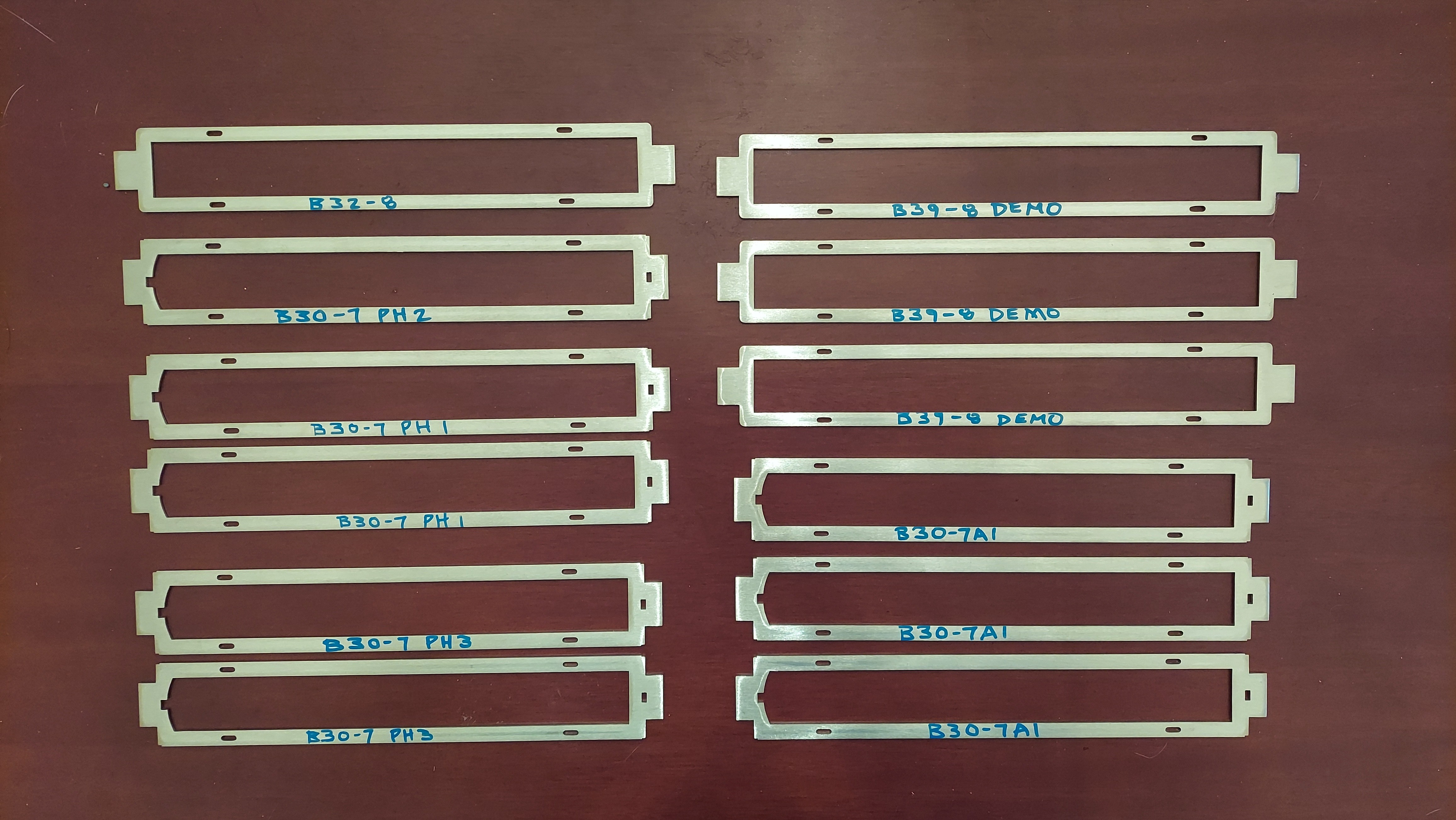
Laser cut stainless steel frames from Send Cut Send


Hybrid nylon and stainless steel frame with Athearn trucks and 3D printed B30-7A1 fuel tank from Shapeways


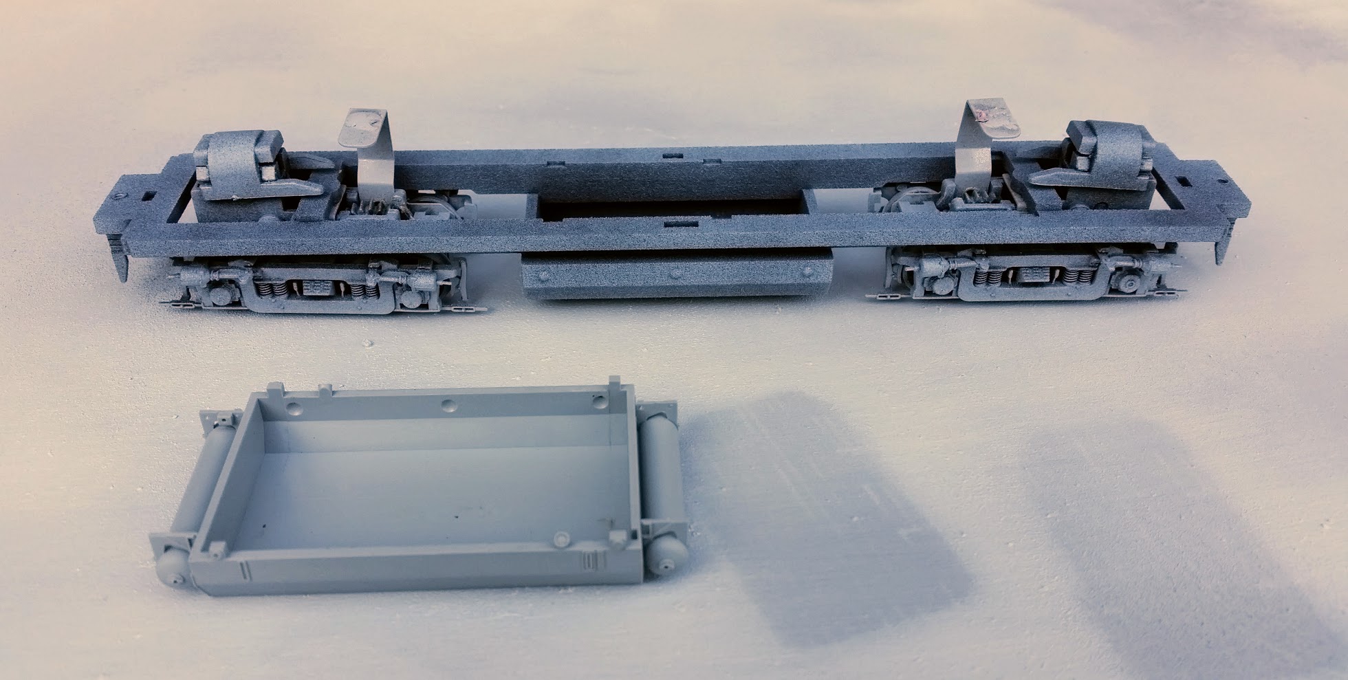
Once I started using MP Scale Models as my printing vendor instead of Shapeways I was able to adapt the frame design to resin instead of nylon. This results in a much smoother appearance. The resin material is also easy to cut, sand, drill and tap. Like the nylon material these resin frames don't have much strength on their own but together with the laser cut steel frame they are quite strong.

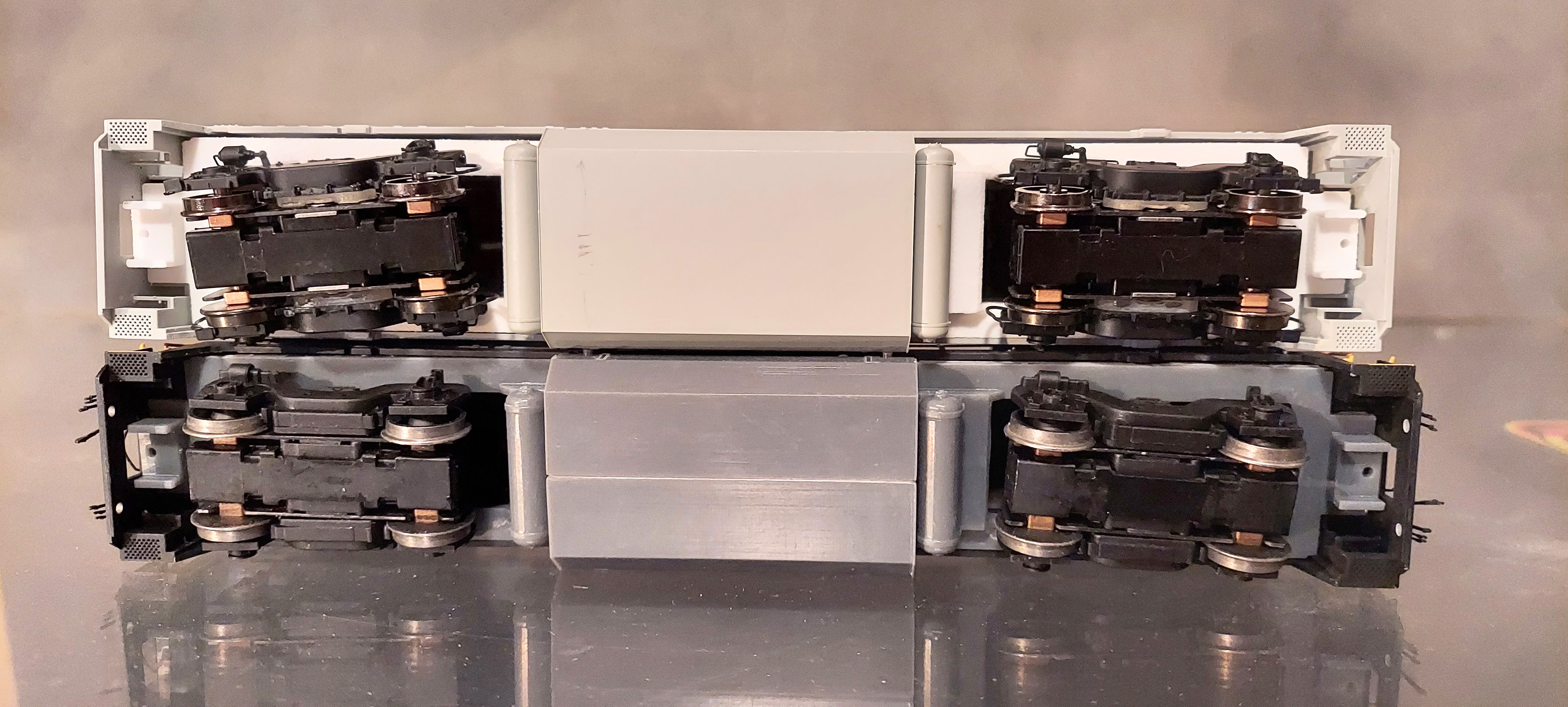
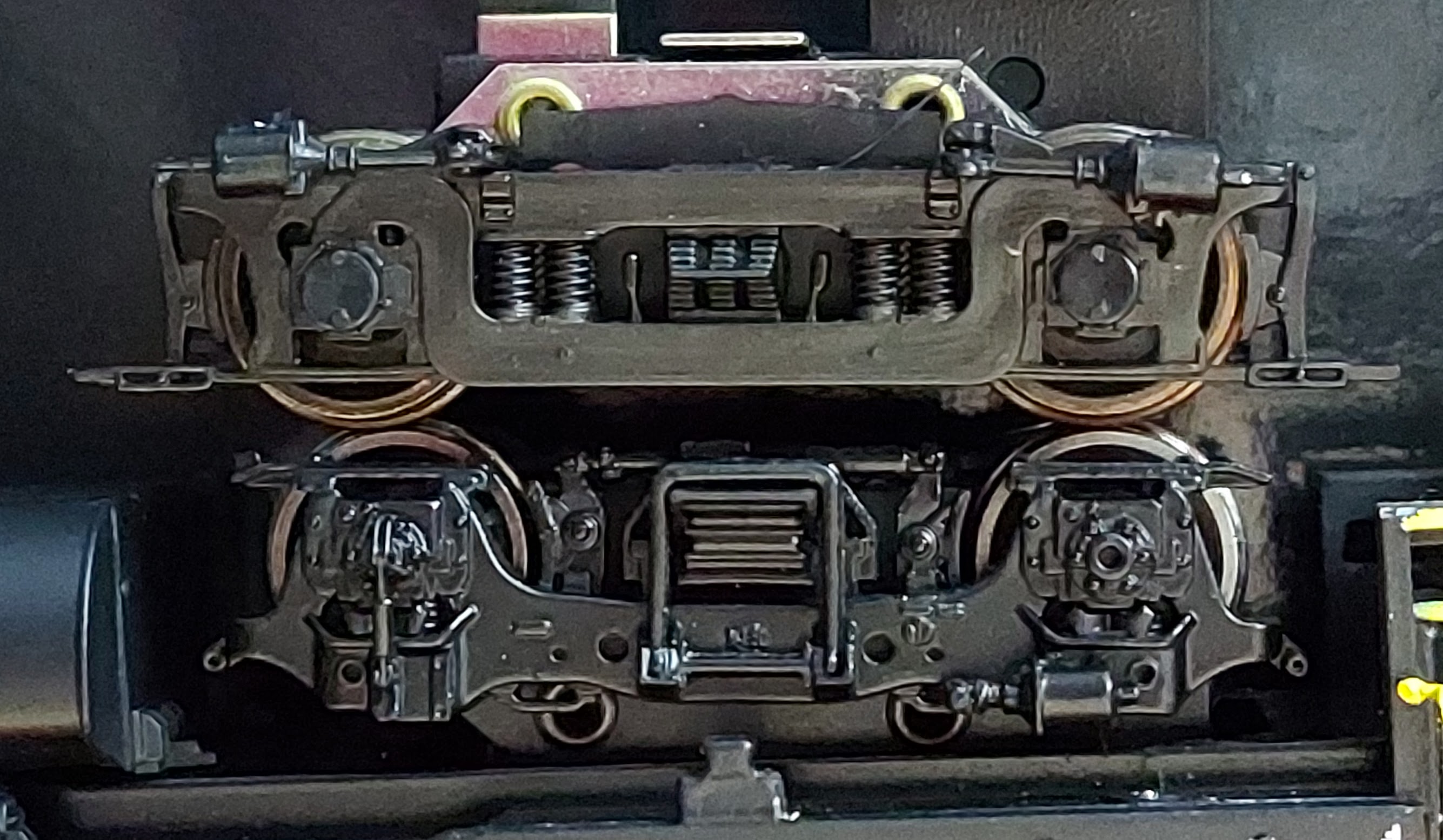
Hybrid nylon/stainless frame on top with dimensionally challenged Atlas fuel tank and skinny but too long reservoirs;
hybrid resin/stainless frame on bottom with resin fuel tank and reservoirs


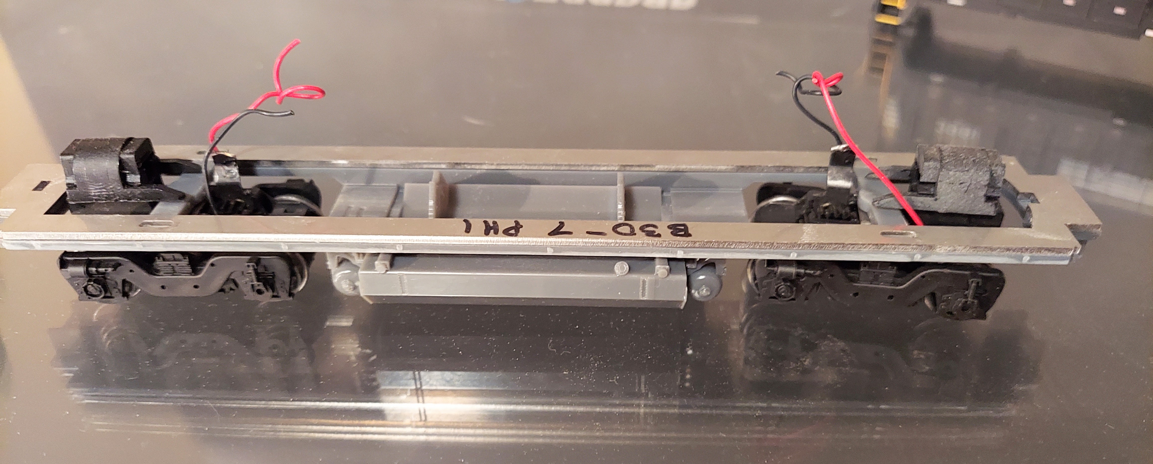
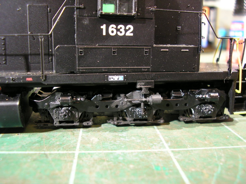
Hybrid resin/stainless frame with resin fuel tank and reservoirs and Athearn trucks with Atlas/Kato FB-2 sideframes


To date all these frame variations are designed to use a Kato HM-5 motor with flywheels, Athearn drive shafts and Athearn trucks. I am working on versions that will use Atlas and Atlas/Kato trucks (such as the AAR B and FB-2 found on the early C424 and U23B models) as well as Atlas and Athearn motor mounts. A-line makes a universal hex drive shaft kit so that is an option if the Athearn hex shafts in various lengths are unavailable.


Trucks


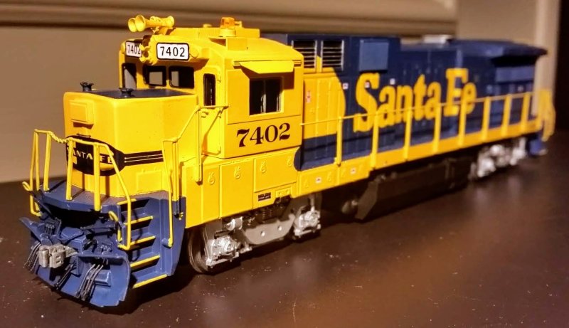
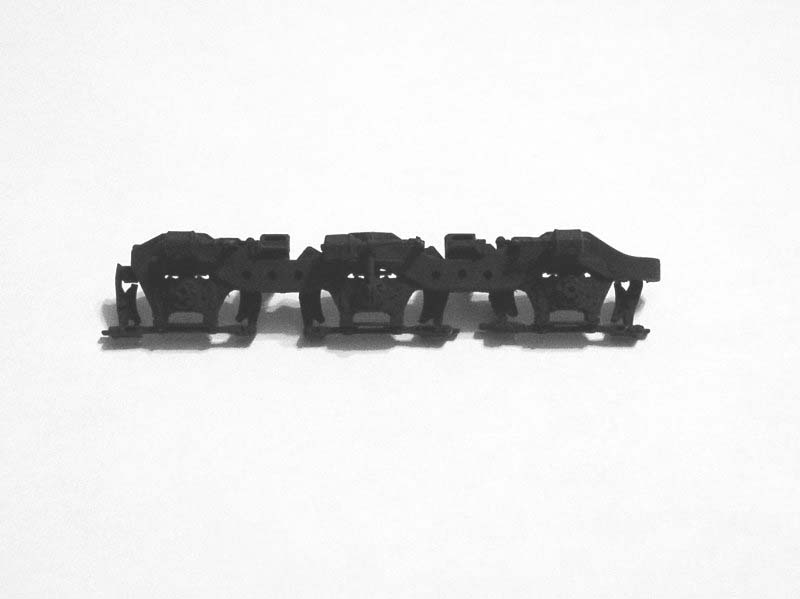
So far I've been working with Athearn and Athearn clone trucks on these kitbashes. They are widely available and the design hasn't changed over the years. Not only that but the Athearn Blomberg sideframes are legendary in their proportions and detail and unmatched by another manufacturer. For SCL/Family Lines/CSX modelers this is great. And for Conrail and Santa Fe modelers the former Life-Like Proto2000 AAR B trucks are a drop-in fit. I'm not certain but I believe Athearn has made their own AAR B truck for the former MDC RS-3, but I have not seen these. Both the P2K and MDC AAR B truck model the longer wheelbase of the prototype accurately whereas the AAR B trucks found on old Athearn U28B, U30B and U33B models are a shortened version of the sideframe adapted to the Blomberg truck.

Blomberg trucks vs. AAR B trucks; Life-Like P2K on top, Athearn on bottom


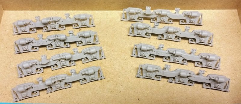
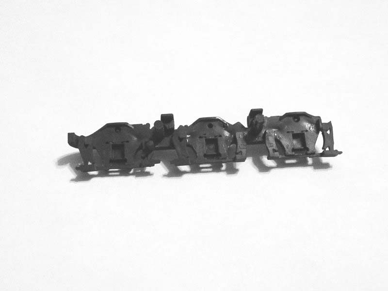
The FB-2 trucks commonly found on most of the Bxx-7 prototypes have been made in HO scale by Atlas/Kato for the U23B, Atlas (China) for the B23-7/B30-7/B40-8 and now by Rapido for their B36-7. Smokey Valley made FB-2 sideframes designed to fit the Athearn Blomberg truck, but they aren't much to look at and they did not fit the truck very well. So I set about ways to correct this problem by adapting Atlas and Rapido sideframes to the Athearn truck. Atlas parts are generally available either from Atlas directly or other third party vendors but Rapido does not offer parts to my knowledge. However, Rapido made a mistake with their original B36-7 release and put the wrong sideframe variants on some of their models. To correct this they offered anyone who bought one of these models a full set of replacement sideframes. I was able to buy some of the "incorrect" sideframes from Rapido customers and adapt them to the Athearn truck. While these are good solutions to adapt existing parts the obvious solution is to draw the FB-2 truck and simply print new sideframes to fit the Athearn truck or the older Atlas/Kato truck.

The hideous crime against humanity that is the Smokey Valley FB-2 sideframe in the foreground, Atlas in background


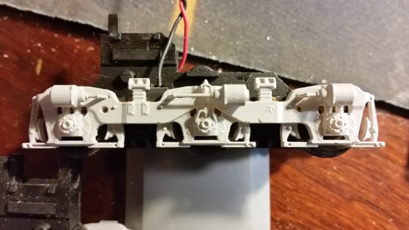
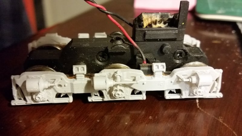
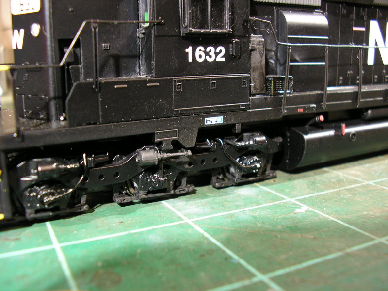
3D printed adapters for mounting the Atlas/Kato FB-2 sideframe on Athearn trucks (these also work for Atlas China parts)


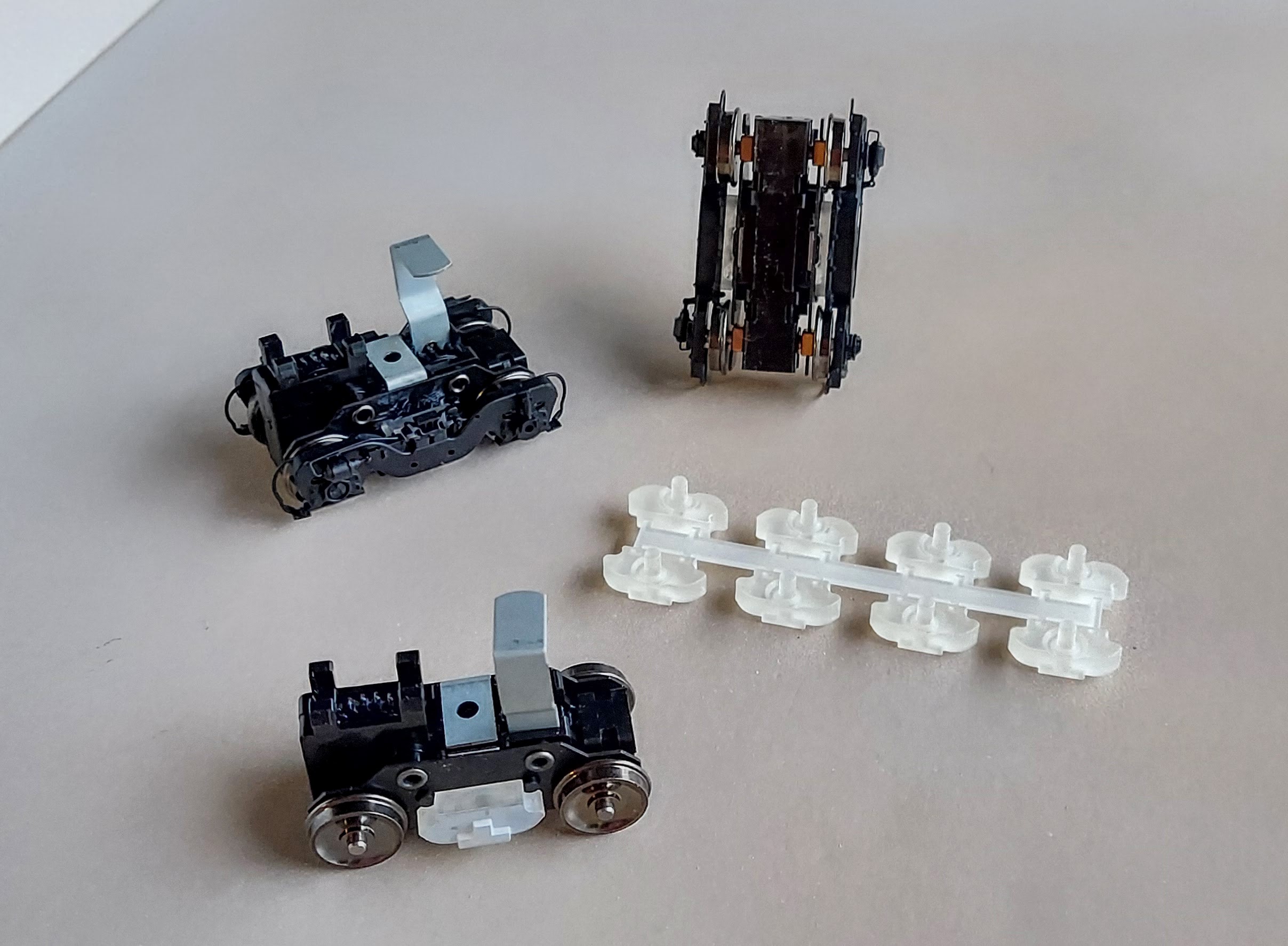
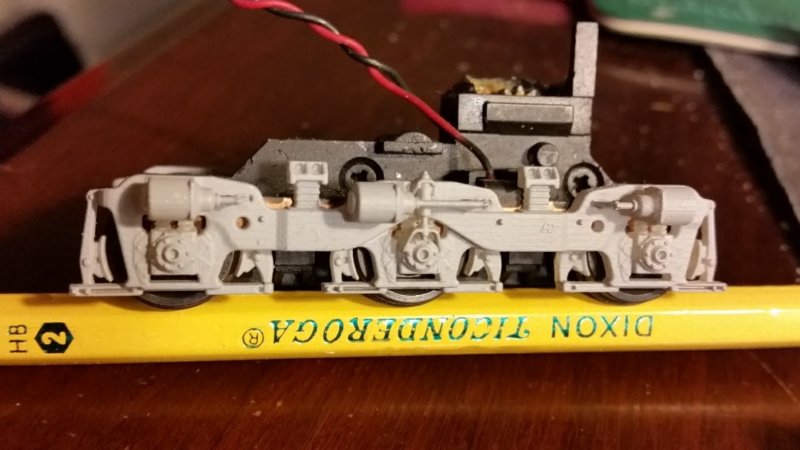
3D printed adapters for mounting the Rapido FB-2 sideframe on an Athearn truck


The Hood


The long hood and nose are the other parts I'm replacing. These are intended to fit the Atlas sill and (until recently) reuse the radiator parts. As I mentioned above an improved radiator part is now being tested to fit the KV Models etched grille.

When I originally started printing through Shapeways I learned quickly the way to get the best results was to design everything as a flat kit. Flat kits were these awful flash-filled ill-fitting things from the 80s that required more work to get usable parts than it did to actually assemble the kit. But the flat kits I've designed and received from Shapeways are nothing like that. If I must heap praise on Shapeways it's for their ability to deliver parts printed exactly the size and shape designed. When I've found a part that didn't fit as intended it turned out I made a mistake in the design. The flat kits I've printed at Shapeways go together exactly as designed and the parts fit quite well whether it's a caboose body or a B30-7AB shell. 

Where I've had a bit of trouble with Shapeways is printing large flat parts. There is a tendency for larger parts to warp so I found that breaking flat kits down to smaller interlocking segments helped keep things square as the kits were assembled. 

B30-7A1B body kit printed by Shapeways


B30-7A1B body kit printed by Shapeways assembled on modified Atlas sill and custom frame


The other problem has always been the price. These kits are not cheap. And after printing in resin the Shapeways acrylic material leaves a lot to be desired in terms of the finish. So the natural progression of the flat body kit is the one-piece resin printed body shell. 

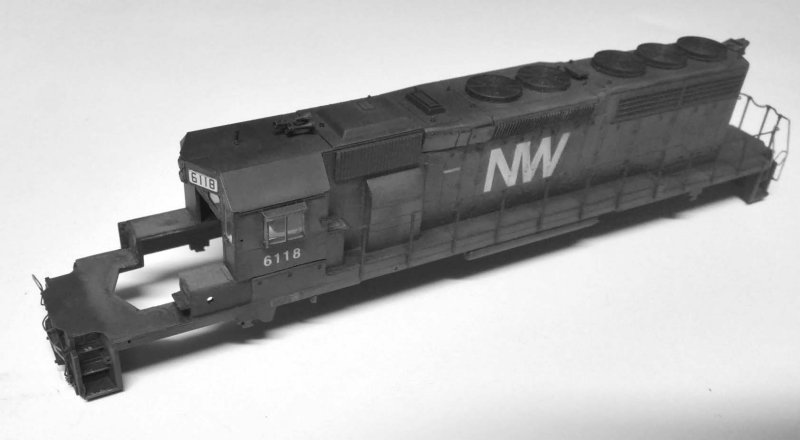
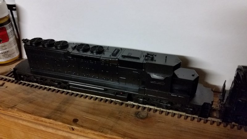
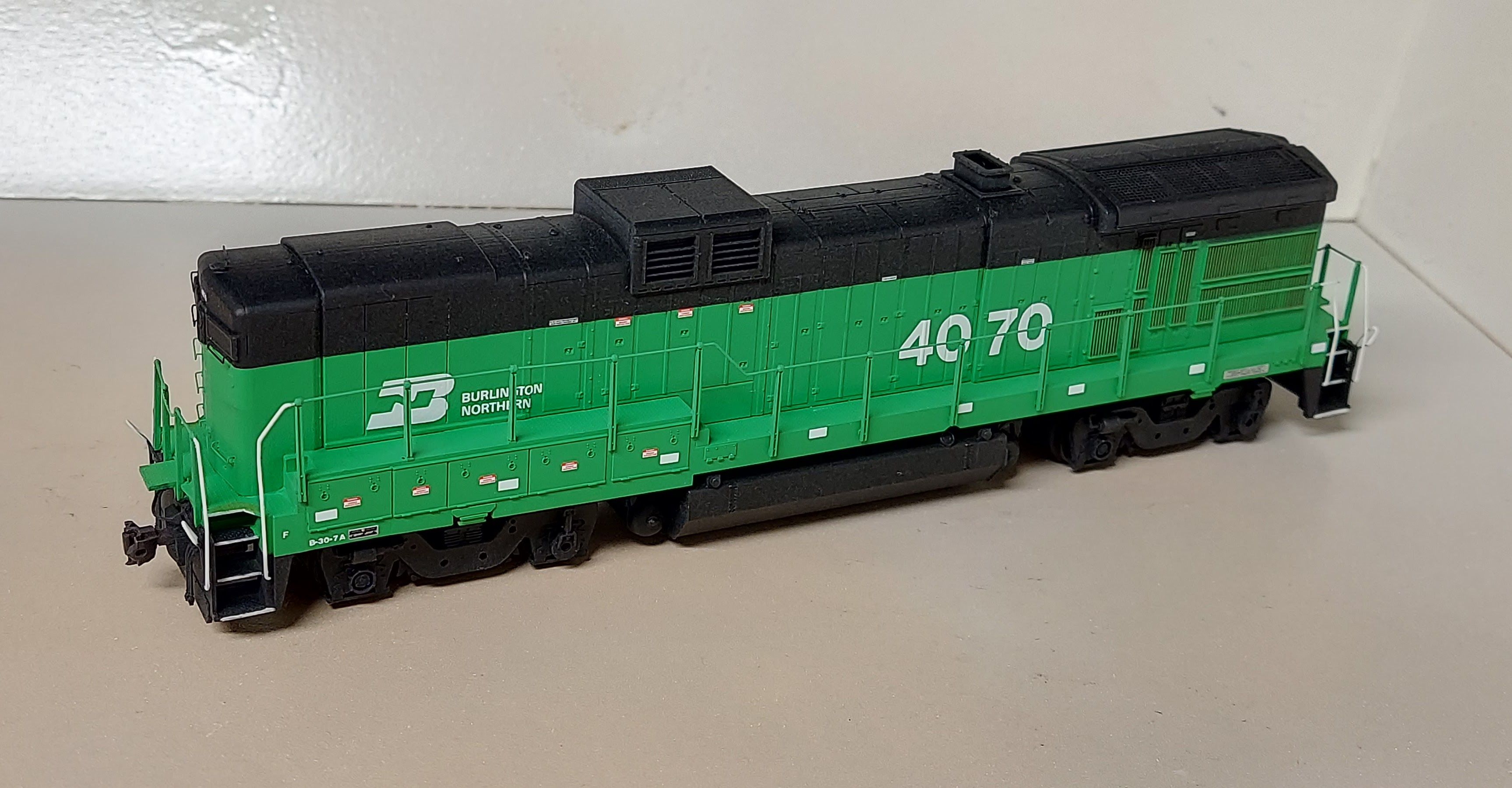
B30-7AB body shell printed by MP Scale Models on modified Atlas sill and custom frame


Like the Shapeways kits some effort must be made to avoid warping but the ease of construction and quality of the finish makes that trouble worth the effort.

With GE models in particular there are so many detail variations within the different phases that it's cost-prohibitive to make every detail for every prototype. Rapido found themselves embroiled in a controversy over a stepwell variation specific to Seaboard when they promised accurate B36-7 models but ignored that variation because tooling up a separate sill part was too expensive. This doesn't have to be a concern with 3D printed parts. In fact, ifwhen there's an error or mistake made in the model it doesn't have to be forever. It can be easily corrected and new parts printed. No expensive tooling must be thrown out and replaced at a great cost. I have made my own share of mistakes (and then some!) but when I catch them I fix them. 

This B30-7A1 nose looks great against the cab, but it's too short and forces the cab too far forward. No sunk tooling costs to absorb and no errors to live with. The CAD file has been revised and a replacement is headed for the printer.

B30-7A1 cab and nose printed by MP Scale Models on modified Atlas sill


...but why male models?


You serious? I just told you that a moment ago.


For somebody who's not reinventing the wheel, it sure seems like there's a lot of reinventing going on. There may be something to that. The fact is, the more I looked at the Atlas Bxx-7 model the more I found to improve. There's no need to address the drive or the trucks, the cab is pretty good and the sill, steps and handrails are just fine. And the Rapido model, while it's an improvement in many ways over the Atlas model, it's expensive and doesn't give many options for modeling other Dash 7 variants (yet). 

But probably the biggest motivator is the cost. If I want to build any of these models I have to start with a powered Rapido model plus a pile of 3D printed parts or I can start with a pile of Atlas parts and a pile of 3D printed parts plus a motor and some trucks. Atlas parts are still cheap but the cost of the 3D printed parts is coming down while the quality keeps coming up. There's not much I can do about the cost of motors and trucks, but it's easy to find good deals on used models on ebay, train shows, swap meets, Facebook and so on. There's no reason why the guts of those used models can't be adapted to a new model.

So that's the future for now: keep on making drawings, making better parts, adapting the 3D printed parts to the good stuff that's out there already. I don't see myself making ready-to-run models out of this adventure. I may not even be able to offer complete kits. But the concepts behind this mess of cut up models and printed parts are viable, repeatable and scalable so that anyone with the right tools could do it.

Friday, March 2, 2018

GE Kitbashes

I have a soft spot for GE locomotives if it isn't already clear. This comes from operating them for a living. The Dash 9s and GEVOs I run every day are powerful, responsive and reliable. It wasn't always that way, though. I don't think anyone disputes the bad reputation GE's Universal series and to a lesser extent the Dash 7 series earned. But once GE started listening to customers report problems, especially as they became involved in solving these problems, things started to turn around.

Real life kitbash: AC4400C4M AC four motor conversion from C44-9W ATSF 608

A big change in railroading was effective dynamic braking. As long as there was an occupied caboose at the rear of the train, train handling meant keeping the slack stretched to avoid throwing your conductor and brakeman out of their seats. To accomplish this the engineer would make a minimum reduction and drag the train over hogbacks and shallow valleys. As dynamic braking technology improved the timing couldn't have been better. New crew consist labor agreements and legislation made cabooses go away for most Class I trains. This freed up the engineer to control the slack without dragging brakes, something the railroads were very interested in because of the massive fuel savings potential, greater average speed, and a lower risk of sticking brakes, flat spots, hotboxes and other problems with the train.

Dynamic brakes had previously been more of a mountain grade feature to augment air braking on long downhill runs than a tool you'd use to control speed on flatter terrain. By themselves they weren't enough to keep heavy trains under control. But through the 70s and 80s the technology was developed to increase their effectiveness and to lower the minimum speed they were effective. With these new capabilities engineers were able to transition between throttle and dynamic braking frequently.

Back when dynamic brakes were used primarily on long descending grades, there weren't many scenarios where the diesel engine would be running hot and demanding cooling from the radiators at the same time the dynamic brakes were dissipating braking force in the form of releasing heat energy through the resistor grids. Therefore it made sense to locate the resistor grids near the radiator where you already had a large fan and intake grilles. But once the ability to transition frequently between throttle and dynamic braking was available, the diesel engine didn't have time to cool while the resistor grids kept the radiator hot. This led to relocating the dynamic brake resistor grids and cooling fans ahead of the diesel engine, first seen on Burlington Northern's second order of B30-7A cabless booster units and C36-7s delivered to Missouri Pacific and Norfolk & Western.

As the use of dynamic brakes moved outside the realm of mountain grades, they became more powerful and more cost-effective to use. Along with the adoption of computer control systems of the diesel engine and electrical systems, design elements of the locomotive had to change to hold up under the new normal extreme operating conditions. These improvements in part led to the Dash 8 series, the wildly successful Dash 9 series and finally to today's Evolution series.

GE wasn't alone in innovation. EMD also computerized their engine and electrical systems around the same time. Like GE, EMD took a new approach with the dynamic brakes on their 50 series locomotives and again with the 80 and 90 series, relocating and improving them each time.

When GE unveiled a new locomotive series it looked like each new design was nothing more than the old Universal series locomotive under layers of bolted on parts. Let's face it: aesthetics were never part of GE's design philosophy when it came to locomotives. Form follows function period. Compare this to General Motors' Electro-Motive Division, where styling was part of the identity of the company from the Corvette to the Cadillac. Look at the homely hodgepodge of a locomotive, the GE B39-8 demonstrator. Compare this to the sleek and aerodynamic EMD GP60 demonstrator, its direct competitor. If looks matter, it's not even a fair fight. But when it came to achieving fuel efficiency, higher horsepower and putting that horsepower to the rail, GE won.

EMD 7 GP60 Demonstrator

ATSF 7402 GE B39-8 Demonstrator

As a modeler it always looked to me like GE simply kitbashed their latest design using parts from previous models. The basic Universal series locomotive had a distinctive cab with a rounded roof, a snub nose and a plain long hood with a rounded roof contour echoing the lines of the cab. This plain hood was punctuated with the occasional grille and a large radiator at the rear. The improved Dash 7 series was just like the Universal series, but with the largest of the large U33 radiators extending out over the walkway. As production carried on Dash 7s had the dynamic brake housing separated from the radiator and moved to a "bump" in the auxiliary cab roof. This bump carried through to the early Dash 8 series and was incorporated into a boxy hood between the operator cab and the engine compartment. U33 radiators were changed out for larger angled Dash 8 radiators.

The Dash 9 series saw the end of the four axle diesel, the standard cab, and the simple angled fuel tank with reservoirs at each end. But with that end came the adoption of large outside coil spring trucks and optional AC traction technology. In the midst of all that was the old Universal series hood covering the engine compartment. Everything else had changed, but that hood was still there (though angled instead of rounded). That feature finally went away with the Evolution Series, along with the Dash 8 radiator, but still around were the comfort cab, the Dash 8 auxiliary cab, the big trucks and the Dash 9 fuel tank.

The apparent modular nature of GE locomotives makes them ideal modeling subjects, especially with so many nicely detailed and great running models from Atlas. The U23B drive and body shell can be combined with the U33C drive and shell to build a U33B, U36B or a U23C. Before Atlas released the B23-7 and B30-7 models, I cut down a C30-7 shell into a B23-7. I had enough trouble with the Bachmann drive -- in particular the trucks -- that I stopped work on the model. The release of the Atlas B23-7 model finally stuck a fork in this project. But the concept was proven, that with enough slicing and dicing the raw materials were there in the Atlas shell parts to build a variety of models.

GE B23-7 from Atlas C30-7 long hood and nose, Atlas U23B cab and Bachmann B23-7 frame and sill

Of course 3D printing has opened up an entirely new set of possibilities using modular components to either cut into the Atlas shell or even replace entire parts. I mentioned building a model of a late C36-7 in my Norfolk & Western clasp truck blog. At the time I didn't address the stacked horizontal radiator intake grilles because there was no good source of the grilles. I couldn't figure out how to scratchbuild them or where I might get something reasonably close to cut in. Besides, the model is painted black. Who can even tell? I finished the model in January 2014 and moved on.

GE C36-7 as NW 8534 from Atlas C30-7, Smokey Valley and Hi-Tech Details parts

A couple years later it occurred to me I could use the translucent nature of 3D printed acrylic parts to model the see-through nature of the corrugated screen grilles on GE locomotives. I drew up some replacement panels for the area under the radiators on the Atlas model and printed them. I painted them lightly with a dirty brown color, just enough to tint the grilles, then I masked the grilles front and back and painted the rest of the parts the black body color. Installed on the model they look great. If you hold the model up to a light you can see the light come through the grilles. Of course the large metal weight mounted to the frame blocks most of the light, but as a concept it's solid.

NW C36-7 radiator parts available from my Shapeways store


Since then I've designed other hood parts, fuel tanks, air reservoirs, cabs and frames. I'm even working on a body kit for Burlington Northern B30-7A booster units. Where will this end? Who knows? But I'm pretty far from the end right now. There are a lot of models and variations to cover -- and kitbash -- yet.

Sunday, February 25, 2018

Norfolk & Western's triple clasp GEs

Norfolk & Western may be best known as the last railroad to retire their steam locomotives and replace their locomotive fleet with diesels. In the diesel era they were known as one of the last railroads (along with future merger partner Southern Railway) to purchase high short hood locomotives. When other railroads had embraced the idea of using a J-relay valve in the locomotive's independent brake system to produce greater brake cylinder pressure against a single brake shoe per wheel, Norfolk & Western stayed the course of using clasp type brakes and lower operating brake cylinder pressure. Evidence of this could be seen in the trucks used on N&W's six axle diesels. The twelve brake shoes per truck gave them a distinctive look.

I modified a couple Athearn SD40-2s to have clasp type brakes a few years ago. I covered those models in my blog here. The modification to the Athearn trucks is pretty easy and it can be done using either Blomberg trucks or Flexicoil switcher trucks to donate the brake shoes, although the Flexicoil switcher trucks will also provide the brake cylinder with the long push rod. It also helps that the Athearn sideframes are made from styrene, which is easy to cut and splice and glue together.

Triple clasp sideframes on Athearn RTR SD40-2

It's another story entirely if you're modeling anything GE, with the exception of the last order of C36-7s. In fact, not having the ability to model the Adirondack clasp type sideframes found on N&W's U30Cs, C30-7s and early C36-7s is the reason I chose to model one of the later C36-7s. Atlas originally made two different sideframes for the U33C and C30-7 models, which they called GSC and Adirondack sideframes after the casting foundry of each prototype. However, Atlas mislabeled the parts which caused great confusion for people trying to get the "correct" version for a particular model.

Atlas GSC C30-7 sideframe

Atlas Adirondack C30-7 sideframe

When Atlas came out with the U30C, another style of sideframe was offered. This time it was a later Adirondack sideframe with low mounted brake cylinders.


This style of sideframe holds the most promise for someone wanting to build some N&W clasp style sideframes. It has the correct shape overall as well as in the area over the brake cylinder lever. Unfortunately the brake cylinder lever at the top of the sideframe exists only to tie onto the handbrake chain, so this shape is only found on the left axle when looking straight at the sideframe. You'd need this shape along with a mirror image of it to cut and splice these sideframes into models of the clasp type, and that's assuming you could actually get the slick engineering plastic the sideframes are cast in to glue back together.

These sideframes, like the National Uni-Truck II (found on some Trailer Train Front Runners, Southern's Autoguard articulated autoracks and under the ends of Burlington Northern's Trough Train articulated coal hoppers) represented something of a holy grail for me. Once I became familiar with the idea that 3D printing could reproduce fine enough details in a durable enough material for modeling I knew I had to take up the challenge to create a CAD model of them.

It's one thing to decide to make a 3D model of something rare and unique and quite another to find enough reference material to make it happen. What was frustrating about these sideframes (and the Uni-Truck II) was they really weren't that rare, they just weren't considered worthy of film during their day. In the digital photography age you just click!-click!-click! until you get the shot. When everyone was shooting film unless you had it in mind you were going to burn a roll or two on detail shots you took your best shots only, well-composed and well-lit. Roster shots of good and poor quality abound from the film era and are easy to find online from a variety of sources. But detail shots of the kind I needed are not so easy to find. If these prototypes still existed in their as-built form today it would be a simple matter of tracking them down and taking some detail photos.

That's actually how the story ends for the National Uni-Truck II. There is a single example of a Front Runner equipped with National Uni-Truck II trucks at the National Museum of Transportation in Kirkwood, Missouri, TTOX 130059. Detail photos of this car provided the information I needed to create the CAD model of the trucks that I ended up printing and offering for sale in my Shapeways store.

3D printed National Uni-Truck II trucks with Intermountain wheels installed on Walthers Front Runner

With the Norfolk & Western U30Cs, C30-7s and C36-7s I wasn't as fortunate finding an example to photograph. I'm not certain on the disposition of all of these locomotives, but many that I've found were shipped overseas after their useful lives here in the United States. Once they arrive at their destination it's not uncommon for them to be converted to a B-B B-B configuration and have the C trucks discarded. I put out a request for photos on discussion forums and email lists a few times over the years but I didn't get a response. That is until the very end of 2017 when Jay Barnaby and Scott Marion hooked me up with some detail photos from their collections. These turned out to be the shots I needed to create 2D drawings.

Some discussion on this topic with Andy Harman was very helpful, too. With the straight-on shots taken care of it became a priority to determine the depth of the features: how much did the brake cylinders protrude from the sideframes, how far did the reinforced section over the center axle protrude, and so forth. More photos were shared and analyzed. And finally in the midst of reverse-engineering the Atlas sideframes to create a drop-in fit of a sideframe I had enough to develop the 3D model.


Here's where I screwed up (there's always that part): I created what may be a perfectly reverse-engineered 3D model of an Atlas GE three axle sideframe. Then I proceeded to install brake rigging on the base sideframe model that fouled the copper pickup and bearing strips that held the axle ends in place, thus preventing the installation of the printed sideframes. Well, that's what prototyping is for! (that's what I tell myself when I screw up with a design) What I should have done is create a 3D model of the truck with the copper pickup strip and checked the fit of the sideframe into the truck model in CAD, not after printing the design. Fortunately, I didn't have to modify the back side of the sideframes much and there was still enough material to hold the brake shoes and levers in place after I removed the material fouling the copper strips. I immediately revised the CAD files to remove this interference.

First printed prototype U30C and C30-7/C36-7 sideframes

Spending all this time working on these clasp sideframes helped me get to know both the Atlas model and the prototypes pretty well. One thing I found interesting about the Atlas model -- and I'm not sure what the reason is for this little nugget of joy -- is the axle spacing in the C truck found on the U33C, C30-7 and U30C. I'm sure it has to do with the prototype of the U33C or C30-7 trucks originally tooled in the 90s by Atlas. The difference is so minor that it probably just wasn't worth addressing when it came time to release the U30C. But it is significant enough that putting the wrong sideframe on the wrong truck will result in a sideframe that won't fit without modification. You'll also notice the bearing detail isn't centered on the center axle and wheelset.

On freight cars there is a B end and an A end. Looking at the B end you have a left and right side. Axles are numbered from the B end to the A end. Similarly, locomotives have a front and a rear. The front is designated by a letter "F" stenciled near the stepwell on the sides of the locomotive nearest the front. Ever the oddballs of the bunch, some Norfolk & Western and some Southern locomotives had their long hoods designated the front, which is in contrast to nearly every other railroad. Fortunately on these GE six axle units the front is the short hood where the operator cab is located. So, when you're looking at the front there is a left side and a right side. Axles are numbered from front to rear.

The prototype uses trucks with a wider spacing between axles 2 and 3 and a narrower spacing between axles 1 and 2. On the rear truck this arrangement is mirrored on the U30C and C30-7, with the greater spacing being between axles 4 and 5 and the lesser spacing between axles 5 and 6. The prototype C36-7 has the same front truck axle spacing as the U30C and C30-7, but the rear truck is reversed. It is not mirrored by the fuel tank. Instead, the front truck is identical to the rear truck. That is, the distance between axles 1 and 2 equals the distance between axles 4 and 5. Likewise, the distance between axles 2 and 3 equals the distance between axles 5 and 6.

The axle spacing on the model is just like the C36-7. This means on the model there is a distinct front truck and a rear truck; the axle spacing is not mirrored by the fuel tank.

If you look at prototype photos of U30Cs and C30-7s, the brake cylinder over the center axle points toward the fuel tank and toward the brake cylinder over the axle nearest the fuel tank. The axle spacing is greater between the two axles with brake cylinders pointing at each other than the spacing between the two axles with brake cylinders pointing the same direction. So if you're following this convoluted description, there is a problem. The axle spacing of the rear truck on the Atlas model will not work with the U30C and C30-7. The Atlas model is actually perfectly set up for the C36-7 since the brake cylinder over the center axles points toward the rear of the locomotive and the axle spacing matches the prototype. But to accurately model the trucks on either a U30C or a C30-7 the rear truck must be a mirror image of the front truck. The easiest way to do this is to replace the rear truck with another front truck. Fortunately, these truck gearboxes are easy to come by direct from Atlas. [Kudos to Atlas for continuing to make parts available and for making them inexpensive. I owe a lot of my GE kitbashes to being able to get Atlas parts.]

I figure that of the handful of others who wish to model N&W U30Cs and C30-7s, only a few will be willing to swap out the rear truck for another front truck. So for those who want to keep the drive stock and simply swap sideframes, I've made a version of the clasp sideframes set up to fit the Atlas drive as-is. For those who want to go crazy and swap rear trucks, I've made a version for them, too.

Finally, here is an image to describe the problem and solution. The sideframes depicted below illustrate the modified parts designed to fit an Atlas model that has not been modified with a front truck replacing the rear truck.


To accommodate the model, the sideframe depicted in the bottom of the image has been modified to match the axle spacing but have the general arrangement of the prototype. You can see the slight difference in distance between the brake cylinder cutouts over axles 2 and 3 and over axles 4 and 5, with 4 and 5 being closer together. On the prototype C30-7 and U30C, the bottom truck should be a mirror image of the top truck.

I'm exhausted from explaining that. You can imagine how exhausting it was to discover during the design process and create a solution for it.

After going through all that, I'm going with the extra front truck on my C30-7 model. Here are the C30-7/C36-7 sideframes:


And here are the U30C sideframes:


Printed Adirondack sideframe compared to Atlas GSC sideframe

One benefit of working up these sideframe designs with such a limited audience is I realized this basic Adirondack design was found elsewhere, namely on early C30-7s purchased by Union Pacific and the C36-7s purchased by Missouri Pacific. It didn't take much effort for me to modify the design to match each prototype.

screenshot of Adirondack sideframe CAD file as seen on early Union Pacific C30-7 locomotives

screenshot of Adirondack sideframe CAD file as seen on Missouri Pacific C36-7 locomotives

One of these days I'll try to run down all the prototypes that used some version of this basic Adirondack truck casting...

Saturday, June 18, 2016

N&W SD40-2

The Athearn SD40-2 has gone through many changes since the model was first introduced. The model was originally sold in the ubiquitous light blue rectangular box with some detail parts and handrails packed separately to be added by the modeler. 

The first revision eliminated the original body/chassis mounting system which consisted of tabs molded onto the body shell and lugs cast as part of the chassis that fit into the tabs. The pilot ends were also closed and the chassis modified to include a coupler box that secured to the frame with a screw, which also served the purpose of attaching the body to the chassis. These modifications were pretty standard for anyone wishing to take the model beyond the blue box and make it a miniature version of the real thing, so it was nice to have the model come this way and eliminate this work.

Some body options were also introduced around this time, including long "snoot" noses, Q-radiator fans, late extended range dynamic brake/exhaust hatches and wire or corrugated radiator grilles. The cast-on grab irons were replaced with starter holes located and spaced for the modeler to install grab irons from Detail Associates. And when the details duplicated the original body details - standard fans, corrugated grilles - they were a much finer, improved version. 

Eventually, molded plastic handrails were included along with the original stamped steel and bent wire handrails that had always been included with the model. Versions of this model were later sold as part of the Ready To Roll series before another round of revisions to the tooling led to the second generation chassis and current body shell with its many variations and options. 

This model represents one from the first revision of the Athearn SD40-2, with wire grilles, improved fans, no grab irons, closed pilots and no external evidence of a body mounting system. Details were added to the factory painted model, including lifting rings, pin lifters, IAM brake lines, sunshade and all-weather window, acrylic "glass", grab irons, a hood end bell and a brass horn.

The prototype Norfolk & Western SD40-2s had clasp type brakes where two shoes press against either side of the wheel instead of the single shoe per wheel common with most other railroads. The separate sideframes of the Athearn model made this a simple detail to correct, and though I had read about different ways to skin this cat, I hadn't tried any of them yet. That changed when I found a spare set of Athearn SW1500 sideframes in my parts box. I noticed the similarities between the SD40-2 and SW1500 sideframes, where the journal is carried between two guides and rests upon a spring assembly. The journals are allowed to move vertically on the prototype and are secured underneath by a retaining device, which also holds the sand hoses. Since the two parts matched each other besides the actual brake rigging, I removed the parts from the SD40-2 sideframes that I intended to transplant from the SW1500 sideframes. I then attached the parts using liquid cement, which is my preferred method and possible because Athearn's sideframes are molded in styrene. The SW1500 sideframes are visible as the gray bits attached to the sideframes. To give an idea of the timeline, this first photo is from 2010 and the most recent from 2016 (I worked on lots of other things during that time!).


Here are some views of a sideframe I modified later:


Here are the same techniques applied to an Athearn SD40-2 from the latest RTR line. The modifications show up as a dull flat black color compared to the rich semigloss black of the factory painted parts:


Okay, so back to the factory painted 6118. I had detailed the model, fixed the trucks and weathered it some. The flat and lifeless fuel tank and air reservoirs needed some attention to match the rest of the model. I filled in some of the casting defects on the tank with epoxy, sanded it and detailed it with Cannon parts. I replaced the air reservoirs with Cannon parts as well:


It looked okay at this point, and it got some weathering that dulled down the paint but something always stuck out when I'd compare it to prototype photos. Eventually I figured it out: this model didn't match the later SD40-2s with brakewheels and corrugated grilles and it also didn't match the earlier models with wire grilles and a ratchet handbrake. As I contemplated installing a ratchet brake from a Cannon nose kit it hit me that this model had the rare combination of an 88" nose and wire grilles. It should have an 81" nose with those grilles or I could keep the nose and replace the grilles. I could do either modification and keep the paint, but now that I had one of the Athearn RTR units in this same paint scheme I began to think I'd prefer one in the final N&W scheme with the name spelled out on the long hood. So with a full repaint on the table I made my decision:


The next step was to mask the clear parts and repaint. Fortunately I had some Seaboard U-boats ready for paint at the same time so I mixed up some warm gloss black and fired up the airbrush. Here's what I use to make that "warm black" and it doesn't take much more than a few drops of brown or tan per teaspoon of black: 


I used the Microscale set for 1982+ N&W diesels along with the diesel data set to go from 6118 to 6082:


Still plenty more details to add, paint to touch up, lighting to install, and weathering to apply. But the weather's hot and dry now so it's time to keep painting!